Wash Select II ™ and Wash Select II ™ POS Installation Manual Unitec www.StartwithUnitec.
W A S H S E L E C T I I WASH SELECT II INSTALLATION MANUAL This manual provides comprehensive operational procedures for the Wash Select II. In this manual, we will discuss the setup, operation and maintenance of the Wash Select II. If further assistance is needed, please contact the distributor from which the product was purchased.
W A S H S E L E C T Table of Contents 1 Site Planning ...................................................................................................................................1 1.1 Electrical Planning......................................................................................................................1 1.1.1 Site Grounding Considerations: ...................................................................................................1 1.1.
W A S H S E L E C T 4.7.1 Connecting a 2-wire Intercom System .......................................................................................23 4.7.2 Connecting a 3-wire Intercom System .......................................................................................23 4.7.3 Connecting a 4-wire Intercom System .......................................................................................24 4.8 Wiring External Fleet Device Interface..............................................
W A S H S E L E C T Index of Figures Figure 1. Conduits with Modem Line Layout.................................................................................... 2 Figure 2. Conduits with Ethernet Cable Layout ............................................................................... 3 Figure 3. Wash Select II Base Placement ....................................................................................... 5 Figure 4. Wash Select II Installation .................................................
W A S H [ T H I S Document Number: Document Title: P A G E I N T E N T I O N A L L Y WS21001 Wash Select II POS Installation Manual L E F T S E L E C T B L A N K ] iv I I
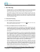
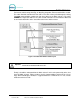
W A S H S E L E C T I I 1 Site Planning The Wash Select II is a self-serve unattended automatic car wash entry system designed specifically for the self-serve car wash market. The Wash Select II accepts various forms of payment, interacts with customers at the car wash entrance, and arms the car wash. It is important to consider a few points prior to the actual installation of the Wash Select II unit.
W A S H S E L E C T I I not be run in the same conduit as the main power lines. Telephone, as well as intercom connections, can be run in the POS4000 connection conduit (Wash Select II POS system) if you are connecting to a POS4000 in a C-store. Figure 1.
W A S H S E L E C T I I For Internet credit clearing, Kwik Trip, or WashPay integration, Ethernet cable will be needed. This cable should be standard CAT 5 or CAT 6. This cable can be pulled through the existing POS4000 communications conduit run from the C-Store to the Wash Select II. The cable CANNOT be longer than 295 feet. The cable should extend at least 2 feet into the WSII and be run into the back office of the store/office to the frame switch or router. Figure 2.
W A S H S E L E C T I I 1.2 Mechanical Planning 1.2.1 Position of the Unit The proper positioning of the Wash Select II unit is very important. Figure 2 of this section should be used as a reference for good layout practices. There are several layout considerations that follow, which may be a good idea to think about. They are meant for suggestion only, and are not permission to circumvent wash manufacturer guidelines.
W A S H S E L E C T I I Figure 3. Wash Select II Base Placement 1.3 Miscellaneous Planning 1.3.1 Precautionary Considerations A large percentage of sites contain “Floor Heat”. Floor heat is an under-concrete heat exchanger system, consisting of an elaborate network of plumbing, through which anti-freeze circulates. In many cases this plumbing can run beside, under, or over conduit.
W A S H S E L E C T I I Installation & Operation Manuals Keys & Lock core set (4) Bolts to secure top assembly to optional base (4) Washers to be used on bolts for optional base 1.3.3 Wash Select II – Option Packages The following items should be added to the standard installation checklist, if that specific option was purchased with it.
W A S H S E L E C T I I 2 Tools Required for Installation 2.1 Mechanical Installation Tools It is highly recommended that the Wash Select II be bricked in! All attempts should be made to achieve that end. It is ultimately the responsibility of individual distributors to make this decision, and if the decision is made that it will not be possible, Unitec offers an optional base at an affordable price.
W A S H Document Number: Document Title: WS21001 Wash Select II POS Installation Manual S E L E C T 8 I I
W A S H S E L E C T I I 3 Mechanical Installation Unitec recommends the bricking in of the WSII when installed on property that is not manned or is not in plain sight of station or business personnel. Note: Unitec also recommends the connection of the WSII to a monitored security system in these situations or any situation where vandalism or theft may occur. The use of the included door sensor and a customer supplied shock sensor mounted on the door is recommended as well. 3.
W A S H S E L E C T I I Figure 4. Wash Select II Installation Hint: Most installers may need to increase the protection and organization of the wires that run from the conduit to the bottom of the Wash Select II main cabinet. Flexible conduit can be used to perform this function. The connectors can be attached to the metal conduit by way of PVC cement. 3.2 Installation of the Optional Base This document outlines the installation of the optional base. 3.2.
W A S H S E L E C T Figure 5. Straight Base Figure 6. Angled Base 1. Mark the 4 holes that you intend to drill in order to mount the Wash Select II optional base. Mark the holes with a marker as the base is sitting on top of the concrete. It is important to keep in mind that the conduit run will need to protrude through the large opening in the lower right corner, at least 3 inches.
W A S H S E L E C T 2. Remove the base from the marked location and proceed to drill the holes, using the hammer drill, and the ½” inch concrete drill bit. Ensure that the holes are drilled deep enough to insert the anchor bolts. A good depth is approximately 2”2½” inches from the surface of the concrete. 3. It should be noted that while the anchor bolts are rugged and durable, they could become damaged if struck recklessly.
W A S H S E L E C T I I 2. Set the unit onto the base, and align the four base holes to the pre-cut holes in the Wash Select II. Use the remaining 4 bolts (with washers on) to secure the top unit to the base. This is done by feeding the bolts through the holes in each of the four corners in the bottom of the main cabinet, and then tightening with the 9/16 “ wrench. 3.
W A S H [ T H I S Document Number: Document Title: P A G E I N T E N T I O N A L L Y WS21001 Wash Select II POS Installation Manual L E F T S E L E C T B L A N K ] 14 I I
W A S H S E L E C T I I 4 Electrical Installation 4.1 Wiring the Modem (Option) The modem is optional. If any of the options requiring a modem are present, the following section should be included in the electrical setup. 4.1.1 At the Unit 1. Grasp the telephone cable and measure a length sufficient to route the cable across the back of the Wash Select II unit, and up to the backside of the modem (inside left wall, if present). Follow the existing cable runs avoiding cables falling behind the hopper. 2.
W A S H S E L E C T I I 1. Locate the other end of the phone modem wire. This may have its own conduit run, or it may run inside the optional POS4000 conduit or it may have a junction box leading to the main PLC conduit. Once the end is found, strip back the insulation, and crimp on another R-J11 modular plug. Ensure enough length remains to install a service loop, or reach to a telephone jack.
W A S H S E L E C T I I the router in the C-store and plugged into the J4 Ethernet connector located on the preinstalled expansion board, as follows: Figure 10. Ethernet Cable Wiring Inside the Wash Select II 4.4 Wiring the Car Wash Note: The CPU Guard may require removal prior to the wiring.
W A S H S E L E C T I I 2. Remove this connector from the socket and hold it so that the pin marked #1 is on the left side. Use the screwdriver to open and/or secure the manufacturer wash wires to each of the appropriate Unitec relay locations in accordance with the following table: Table 1. Wash Relays POS4000, Wash Select II CPU board (lower left corner) Location: Signal: Enterlink Equivalent E-system, Wash Select V1 Equivalent Wash Relay Common J-17, Pin 9 PC Conn.
W A S H S E L E C T I I 4.4.3 Wash-Fault Some car wash manufactures include another interface signal to a unit, the WASH-FAULT signal. This signal could have a voltage as high as 115VAC, and the installer is advised to take the necessary precautions during installation. 1. Locate the same connector to which the WIU signal is connected to in section 4.1.5 above, J-18 in the lower left corner of the CPU.
W A S H S E L E C T I I hopper handle, and pulling it out the front. The cable that connects it to the CPU board will need to be removed as well. Once the power connector has been located, proceed with the rest of this section. 4.6.1 Measure Wire Lengths 1. Along with the wires that were already pulled there should be a three-conductor cable for the main 120 VAC power. This cable should be 16 AWG or greater, and should consist of an environmentally rated black, white, and green colored wire.
W A S H S E L E C T Figure 12. Inside the AC Connector 2. Remove the line insulator and set it aside for the next step. Remove the screw holding the stabilizer plate in place and set both aside until after you have finished securing the wires. 3. Thread the power cord (with the 3 exposed conductors) through the hole in the bottom of the line insulator. Continue to feed it through until about ½” of outer insulation is protruding through the top. (See Figure 10) Figure 13.
W A S H S E L E C T I I Figure 14. Line - Neutral - Ground Connections 5. When all of the wires have been attached, pull the rubber insulation cover up to the housing, and insert it into its original location. The three wires should be trimmed back to a length small enough to allow for a tiny portion of the main cable insulation to protrude into the case, without affecting the ease with which the top and bottom pieces could be closed. Screw the stabilizer plate back into its original position. 6.
W A S H S E L E C T Intercom cable 2-wire connection: pin-1 = audio/call feed. Pin-2 = audio/call ground Figure 15. Intercom Adaptor Board 4.7.1 Connecting a 2-wire Intercom System 1. Locate the 2-pin connector on the “Intercom Adapter Board”. (See Figure above.) 2. Use a small flathead screwdriver to loosen the screws on the top of the 2 pin connector. 3. Locate the “Audio/Call Feed” wire of the intercom system. 4. Attach the “Audio/Call Feed” wire to pin 1 and tighten the screw to pin 1. 5.
W A S H S E L E C T I I 4.7.3 Connecting a 4-wire Intercom System 1. Locate the 4-pin connector on the “Intercom Adapter Board”. (See Figure 4.) 2. Use a small flathead screwdriver to loosen the screws on the top of the 4 pin connector. 3. Locate the “Call Feed” wire of the intercom system. 4. Attach the “Call Feed” wire to pin 1 of the 4-pin connector and then tighten the screw. 5. Locate the “Call Ground” wire of the intercom system. 6.
W A S H S E L E C T I I Table 6. J 2 of Unitec Wash Card interface board Pin Number Signal Name Connect to 1 Output 1 N.O. Washcard TB-A pin 10 (Input 5) 2 Output 2 N.O. Washcard TB-A pin 12 (Input 6) 3 Output 3 N.O. Washcard TB-A pin 14 (Input 7) 4 Output 4 N.O Washcard TB-A pin 16 (Input 8) 5 Output Common Washcard TB-A pin 11 (Common 5+6) Table 7.
W A S H Number 1 (Old Version) Output 1 N.O. S E L E C T I I (New Version) Express key JP5a Pin 4 (Button 4) Express key JP5a Pin 4 (Gray) 2 Output 2 N.O. Express key JP5a Pin 3 (Button 3) Express key JP5a Pin 3 (White) 3 Output 3 N.O. Express key JP5a Pin 2 (Button 2) Express key JP5a Pin 2 (Green) 4 Output 4 N.
W A S H 6 10-16VDC- Isolated S E L E C T I I eWash J5 Pin 5 Remove connector J2 from the Ext Fleet card on the lower left of the I/O board and make the following connections. Table 12. J2 of Unitec Wash Card Interface Board Pin Number Signal Name Connect to 1 Output 1 N.O. EWash J1 Pin 16 2 Output 2 N.O. EWash J1 Pin 17 3 Output 3 N.O. EWash J1 Pin 17 4 Output 4 N.
W A S H S E L E C T I I 5 Startup / Programming For the following sections, the Wash Select II unit must be powered and placed into the operational state known as “SETUP MODE”. The unit can be operated as such by placing the toggle switch (located in the top and middle portion of the main circuit board) towards the rear of the unit.
W A S H S E L E C T I I by the (*)-key. All wash prices must be input as cents. For example, a wash price of $4.00 would be entered as (4) (0) (0) (*). 5.1.2 Wash Names Programming customized wash names uses alphanumeric characters. In this application, the (#)-key doubles as a space-bar, as well as moves from one letter’s location one place to the right into the next letter’s location.
W A S H S E L E C T I I No/Pulsed – Relays are turned on for a 2 second pulse when the arming signal is sent to the carwash. The relays will not activate again unless the customer upgrades the wash (if upgrading is enabled). Default Setting is: No/Pulsed 5.2.3 Relay Pattern The Wash Select II is equipped to allow up to 8 relays to be used for programming of wash packages.
W A S H S E L E C T I I 5.2.5 Wash Handshaking Wash handshaking is defaulted to use a “Wash-In-Use” signal, versus a “Cycle Complete”. There should be no reason to change this setting unless the installer is configuring to interface using “Hamilton Mode”. Operation in this mode will cause the “Cash Upgrades” to be automatically disabled, and also cause the “Automatic By Price” mode to revert back to “Forced Selection”, if either one was set.
W A S H S E L E C T I I is listed at $5.00. They proceed to insert a five-dollar bill and the Wash Select II instantly issues a command to run the $5.00 program, instead of giving them the option to make a selection (or ever giving their dollar back in change). Careful consideration should be given to how this feature will be configured. The Wash Select II unit is ENABLED by default, and should be changed only if the wash types are more expensive and buy-ups are permitted. 5.3.
W A S H S E L E C T I I the lights is blinking, you may have a failed connection, or a failed POS4000. A failed communications module is also possible. 4. Enter the POS4000 Link sub menu and enable the interface by enabling the “Interface Mode”. 5. If you have a multi-bay system, you will have to set the bay addresses (Wash 1 is Bay 2, Wash 2 is Bay 3 etc). 6. Set the unit to “Operate Mode”.
W A S H S E L E C T I I Begin with the master unit. 1. Enter the POS4000 Link sub menu and set “Interface Mode” to 2, “Multi-unit Link”. 2. Proceed to “set bay address” in the POS4000 Link menu. 3. If you are setting up the master, then set the bay address to 1. 4. After this, the Wash Select II automatically asks for NUMBER OF BAYS. 5. The number of bays is equal to the number of Wash Select IIs in your system. If you have two Wash Select IIs (one master + one secondary), NUMBER OF BAYS = 2.
W A S H S E L E C T I I Multi-Coin Acceptors: If you have the multi-coin acceptor (IDX), and wish to program site-specific tokens, please refer to the Operating manual for programming instructions. 5.7 Testing the Entry System After performing the installation and programming, you must test the Wash Select II. Each of the tests that follow is designed to test a specific aspect of the Wash Select II functionality. Before testing the entry system, a few things must first be verified and/or completed.
W A S H S E L E C T I I 2. Verify that every wash purchased gives the proper wash package at the car wash side. Make any adjustments on relay output wires that may be required, and verify that the Wash-In-Use signal resets the controller electronics. 3. Pull the car wash relays connector (J-17 on CPU), and proceed to purchase all of the washes again, by using tokens, quarters, and a fleet account code.
W A S H [ T H I S Document Number: Document Title: P A G E I N T E N T I O N A L L Y WS21001 Wash Select II POS Installation Manual L E F T S E L E C T B L A N K ] 37 I I
W A S H S E L E C T I I Appendix A. Guide for Alternate Keypad Functions This diagram shows all of the alphanumeric keypad functions available with the standard Wash Select II keypad. To access these items, the unit should be in the test mode and within a menu that requires data to be entered as text. Each of the keys can be depressed multiple times to scroll through the various available symbols. Example 1: The key marked 1 can be used to input the letters ‘A’, ‘B’, and ‘C’, and the symbols ‘$’ and ‘:’.
W A S H [ T H I S Document Number: Document Title: P A G E I N T E N T I O N A L L Y WS21001 Wash Select II POS Installation Manual L E F T S E L E C T B L A N K ] 39 I I
W A S H S E L E C T I I Appendix B. Recorded Speech Messages Recording custom speech messages is accomplished by connecting the supplied microphone into the Speech Module microphone plug located under the clear cover over the CPU board. Speech programming is initiated by using the “Speech” menu in “Setup Mode”. Directly underneath the CPU cover is a small, piggybacked circuit board with a black volume control knob protruding straight out. This is called the “Speech Module.
W A S H S E L E C T I I 6) PACKAGE 4 PURCHASED (8.5 seconds) You have purchased the Works Wash. You may enter the wash if it is ready. 7) CODE INVALID (4.25 seconds) Your code is invalid. Please try again. 8) RECEIPT PROMPT (4.25 seconds) Would you like to have a receipt? 9) AUTHORIZING (5.75 seconds) Please wait while your card is being authorized. 10) CARD FAILURE (5.75 seconds) Your transaction was not authorized. Please try again or use another payment method. 11) HOPPER FAILURE (8.
W A S H 19) NETWORK ERROR S E L E C T (4.25 seconds) Sorry, we were unable to process your transaction at this time. 20) SELECT CREDIT/DEBIT (3.25 seconds) Please select Credit or Debit. 21) ONE MOMENT PLEASE (2.50 seconds) One moment please. 22) BAD CARD ORIENTATION (5.75 seconds) Please check your card orientation, stripe to the right. 23) CREDIT TERM CUSTOM (5.00 seconds) (Customized Credit Terminal Decline Message) 24) SELECT AN OPTION (3.25 seconds) Please select an option.
W A S H [ T H I S Document Number: Document Title: P A G E I N T E N T I O N A L L Y WS21001 Wash Select II POS Installation Manual L E F T S E L E C T B L A N K ] 43 I I
W A S H S E L E C T I I Appendix C. Paging Error Codes Numeric Pager format: #####XXXXX Where ##### is Site ID (misc menu) And XXXXX is carwash Error Code Text format is: Carwash ##### MMMMMMMMMMMMMMMM Where ##### is Site ID (misc menu) And MMMMMMMMMMMMMMMM is the carwash error code in text format Table 17.
W A S H Error Code # (Numeric) Text Name (Text/TAP) Detailed Description S E L E C T I I Problem Type Priority (Voice/ Tone) Lower Tolerance Upper Tolerance 9 PRINTER PWR ERR No 24VDC power to printer Warning 2 1 2 10 PRINTER ERROR Printer is either disconnected, malfunctioning, or paper head arm is disengaged. Warning 2 1 2 11 BILL JAM A bill is jammed in the bill validator. Warning 2 1 1 12 BILL STACKER FULL The bill stacker needs to be emptied.
W A S H S E L E C T I I Appendix D. Additional Steps for Canadian WSII Install This section gives a description of what makes the Canadian WSII different form the US version. If you cannot find a piece of information that you think is pertinent to the Canadian WSII, and is not mentioned here, it must have been true for both the US and Canadian versions and you should be able to find it in other sections of this manual.
W A S H S E L E C T I I NOTE: You can do this only for the standard Canadian WSII (accepts all quarters, $1 and $2 coins, and tokens). Remove the coin acceptor label that reads “Quarters, $1 & $2 coins, Tokens” from the front of the door. Replace the new label that reads “$1 coin, $2 coin, Token”. Put unit in setup mode. Go to Diagnostics main menu. Go to the “Test bills/coins “ sub-menu. Open the cover of the IDX acceptor. Turn the rotary switch of the IDX to position 5.
W A S H S E L E C T I I 3. If you are accepting quarters: 1. Remove the front cover by pushing in and up at the bottom right corner of the main body of the unit (near the phone number printed on the cover). 2. Find the rotary-switch and set it to the position labeled number 6. 3. Press the button immediately to the left of the rotary switch once. 4. Drop the 6 quarters through the acceptor. The IDX will blink once after each coin.
W A S H S E L E C T 2. Press the button to the immediate left once 3. Drop the six sample tokens and note that the LED blinks multiple times after the last token 4. Set the rotary switch to position 2 5. Press the button twice (for 2 pulses or $2) 6. Drop the six sample tokens of the second type, and note that the LED blinks multiple times after the last token 7. Replace the rotary switch to 0 8. Replace the cover Refer to the following table for your token information. Table 18.
W A S H S E L E C T I I NOTE: The IDX coin-acceptor can be programmed to divert either the $1 coin or a quarter. The diverted coin needs to be programmed to be on pin 6 of the IDX always. The table below lists the programming structure. Table 19.
W A S H S E L E C T 8. If you are still having problems, check if the modem is powered. Also check if the modem cable is well connected. And repeat the process. 9. If you are still having problems, go to the Diagnostics main menu, and choose “test modem” command. If the modem responds with an OK message, try to open a batch again. 10. If you are unable to do so at this point, then you might have a modem with the wrong programming.
W A S H S E L E C T 12. If you have any clues from the printout, proceed to open the batch after solving the problems. 13. If you are still experiencing problems, modem might be bad. Contact Unitec. 14. You are now ready to do business via credit. You can return the unit back to operate mode via the setup/operate switch. 15. If you, for any reason, change your mind to resort to manual batch opening/closing, all you have to do is repeat step 5 above- this time, set “processor type” to zero.
W A S H [ T H I S Document Number: Document Title: P A G E I N T E N T I O N A L L Y WS21001 Wash Select II POS Installation Manual L E F T S E L E C T B L A N K ] 53 I I
W A S H S E L E C T I I Appendix E. Single Gate Installation (Without Gate Controller) The Barrier Gate option allows you to place a gate in front of the Wash Select II unit to control the flow of traffic into your car wash. A Gate Controller is not required when the site uses a single Wash Select II and a single barrier gate to control access to the tunnel wash.
W A S H S E L E C T I I 1. Electrical Planning In addition to the standard three conduits carrying wash signal wiring, communications wiring, and AC power wiring, you will need the following: A conduit between the Wash Select II and the barrier gate to carry 115120VAC wiring. A conduit between the barrier gate and the Wash Select II unit to carry signal wiring. A short conduit between the gate reset loop and the gate.
W A S H S E L E C T I I Figure 21. Gate Position 3. Mechanical Installation You will be installing the gate directly into the concrete slab. Mark the position of the gate for conduit reference (see gate installation documentation), and then cut the gate loops appropriately. You will need to run a conduit from the loop to the gate to hold the gate loop leads. Conduit should be PVC only. a) Gate Reset Loop Each gate requires one gate reset loop. The gate reset loop should be 6’ long by 2.5’ wide.
W A S H S E L E C T I I With the dimensions as specified above, you will need to loop the wire 5 times around the loop. Cut the loop according to the guidelines provided in the installation documentation that comes with the gate. b) Installing the Gate The holes in the base of the gate are 3/4" in diameter. The mounting bolts must be 3/8” in diameter. Figure 23. Gate Base Bolt Positioning 4.
W A S H S E L E C T 6. Connect the gate reset loop leads to terminals 15 and 16 inside the gate. Refer to the following table when wiring the Wash Select II unit to the barrier gate. Wash Select II Phoenix Connector Pin Gate Terminal J18, pin 1 50 J18, pin 2 1 J19, pin 1 42 J19, Pin 2 52 N/A 48 22 The following diagram illustrates the proper wiring at the gate: Figure 24.