Sentinel Installation Manual Unitec 443-561-1200 • www.StartwithUnitec.
S E N T I N E L SENTINEL INSTALLATION MANUAL Revision A This manual provides comprehensive installation procedures for the Sentinel. It includes the process of site planning, site preparation, the mechanical installation of the SentineI and the electrical wiring of the unit. If further assistance is needed, please contact the distributor from which the Sentinel was purchased.
S E N T I N E L Table of Contents 1 Site Planning and Preparation ......................................................................................................1 1.1 Introduction ............................................................................................................................1 1.2 Positioning the Sentinel .........................................................................................................2 1.2.1 In-Bay Applications ...............................
S E N T I N E L Appendix A. Sentinel Base - Bottom Up View ..............................................................................20 Appendix B. Sentinel Networking ..................................................................................................21 Appendix C. POS Interface External POS Option.........................................................................27 Index of Figures Figure 1. Express Exterior Island.............................................................
S E N T I N E L 1 Site Planning and Preparation 1.1 Introduction This chapter provides guidelines for planning the Sentinel installation and preparing the site. preparation includes: • Determining how and where the Sentinel will be mounted • Installing conduit runs and required wiring Site These instructions serve as general guidelines only. If your wash manufacturer’s installation requirements differ from these guidelines, always meet the wash manufacturer’s requirements first.
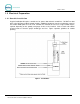
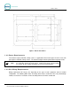
S E N T I N E L 1.2 Positioning the Sentinel 1.2.1 In-Bay Applications For in-bay automatics and other applications where the Sentinel is installed at the wash entrance, it should be placed 10’-14’ from the wash to ensure the proper timing and flow of customers. For curb mount applications, the front surface of the Sentinel should be even with the edge of the curb. To achieve this dimension, the base frame should be installed so its leading edge is 7 in. from the edge of the curb. 1.2.
S E N T I N E L Figure 1.
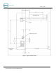
S E N T I N E L 1.3 Electrical Preparation 1.3.1 Conduit Installation A typical installation will require 3 conduit runs for, power, data and wash control lines. DO NOT run data wires in the AC Power or Wash Control conduits. Additional conduit runs may be needed when a gate or the Sentinel RFID option are to be used. Conduit size should be at least ¾ in, a larger conduit may be required depending on the quantity and gauge of wires to be installed.
S E N T I N E L Figure 3. Bottom View of Base 1.3.2 Power Requirements The Sentinel requires 120 VAC, 8 Amps service. In applications where barrier gates are to be used, each gate requires 120 VAC, 5 Amps service. The Sentinel and gate must be powered from separate circuits. Note: Ensure the protective earth ground wires do not carry any motor return current. Only the neutral wire should carry return current. Follow local electrical code when wiring the Sentinel.
S E N T I N E L Circuit Description Wire Qty Wire Requirements Sentinel Power (115-120 VAC, 8 Amps). 3 16 AWG minimum, black/white/green Gate Power (115-120 VAC, 5 Amps).
S E N T I N E L 2 Mechanical Installation 2.1 Hardware Required Prior to beginning the installation, take the time to verify that all the following required parts are present and accounted for. Items supplied with the Sentinel: • Allen Wrench For Door • Key set for door • Key set for vault door • IEC-320-C14 Female AC Power Connector Items supplied with the Base: • (6) ½: Hex Nuts • (6) ½” Flat Washers • (6) ½” Lock Washers 2.2 Recommended Tools 2.2.
S E N T I N E L 2.3 Base Installation Note: Pull all wires through conduits before mounting the base. See Electrical Planning for wiring requirements. The Sentinel base frame is designed to be embedded in a concrete pad, but can also be surface mounted in cases where concrete has already been poured. Unitec highly recommends that the base be embedded into concrete, because using this method makes the unit more secure and less likely to be able to be removed by a truck with a chain.
S E N T I N E L Figure 5. Sentinel Base with Mounting Plates When the base is to be surface mounted, the legs of the frame will need to be cut so that the appropriate mounting plate can be bolted to the concrete surface. The cut edges of the pipe should be coated with a rust preventative paint to deter corrosion. The frame is to be secured to the concrete using the (6) concrete anchor bolts provided.
S E N T I N E L 2. Carefully set the Sentinel on top of the base so the (3) studs of the base pass through the mounting holes on the bottom of the Sentinel. 3. Secure the Sentinel to the studs with the flat washer, lock washer and hex nut (in that order) supplied with the base. 4. Pull the wires up through the cable entrance ports on the bottom of the Sentinel enclosure. 5. Verify the unit’s final position. 6. Use the dual-plane level to verify that the unit is level.
S E N T I N E L Figure 6. Sentinel Interior 3.4 Connecting Power 1. Locate main power wires. There will be three 16 AWG (or greater) environmentally rated black, white, and green colored wires. 2. Route the main power wires up through the conduit to the Sentinel’s power panel. Remove excess wire length, leaving sufficient length to reach the power panel. Remove the plastic shield on the power terminal block. 3.
S E N T I N E L Figure 7. Neutral - Ground – Line Connections 4. Use wire ties to route and secure any extra cable. Replace the plastic shield. 3.5 Network Connection The Cat 5 cable will need to be terminated at each end with an RJ-45 modular plug. This termination should be performed by a technician who is experienced in assembling network cables as a slight misalignment in the wire termination can cause communications problems.
S E N T I N E L 3.6 Wash Control Wiring 3.6.1 Overview In applications where the Sentinel will communicate with the Wash Controller, the wash control wires will need to be connected to the Wash I/O Board. Most wash manufacturers use a five-wire system to provide the arming signals for the selected wash packages. One common line and four arming input wires are fed from the wash’s PLC to the Wash I/O board.
S E N T I N E L Note: “Wash Output #”refers to the number associated with the arming wires. Refer to the wash manufacturer documentation for more information. 4. Connect the wash relay arming wires, the wash relay common wire, and any spare option relay wires to the appropriate pins, as indicated in the following table. Use the screwdriver to open and/or secure the manufacturer wash wires to each of the Unitec relay locations. Table 1.
S E N T I N E L • Make sure all power is disconnected from the wash equipment prior to beginning this procedure. • You will need a thin tipped, flat head screwdriver to open and tighten the relay connections of the Phoenix connector. • Review the wash manufacturer’s documentation to determine the color codes for the wiring of the wash pin-outs for your wash equipment before beginning this installation.
S E N T I N E L 3.7 Intercom Systems 3.7.1 Overview The use of an intercom system allows two-way communications between customers at the Sentinel and staff elsewhere on site. A customer activates the Sentinel’s intercom output by pressing the help button. Without an intercom, the intercom output can be used to activate a bell, light or other device to alert an attendant that help is needed. The intercom wires connect to the Display IO board on the back of the main door.
S E N T I N E L 2 Wire Intercom Configuration: This type of intercom system has both the Call Function and audio sharing the two conductors. Jumper pins 3&4 and 1&2 of J17 and connect the two conductors to SP+ & SP-. 3.8 Camera Connection The (optional) surveillance camera is attached to the front door of the Sentinel. The camera is intended for use with a DVR or similar monitoring device installed at the site. The coaxial cable routed to the camera is used to connect it to the monitoring device.
S E N T I N E L 4 System Startup For fully detailed instructions, please see the Sierra Management Application Programming Manual on the www.StartwithUnitec.com website. 1. Power up the Sentinel. 2. Using a laptop, login into the Sierra Management System. 3. Enter the Site information and credit networking information, wash information, and setup a device profile. 4. Download the device profile. 5. The Sentinel will reboot and be in full operational mode.
S E N T I N E L [ T H I S P A G E I N T E N T I O N A L L Y Document Number: SENT1001 Document Name: Sentinel Installation Manual L E F T B L A N K ] 19
Appendix A.
Appendix B. Sentinel Networking Unitec supplies a pre-programmed router for connecting devices as a local network. The networked devices will vary based on options ordered and may include: • One or more Sentinel units • A Sentinel Console • A POS Interface device (to communicate with a C-store POS System) • A print server (for connecting a local report printer) In cases where there will be more than (4) Unitec devices on the network, an Ethernet switch will need to be added.
S E N T I N E L When a router (or modem with built-in router) is used between the Unitec router and broadband connection, it must be configured to allow external connections to and from the Sentinel. The router should be configured to: • Forward the ports assigned to the Sentinel(s) to the Unitec router. For a single unit installation the port is 9810. In multi-unit sites, the ports would increment for each Sentinel i.e. 9811, 9812 etc..).
S E N T I N E L • Terminating Ethernet Cables 1. Carefully remove the outer jacket of the cable. Be careful when stripping the jacket as to not nick or cut the internal wiring. One good way to do this is to cut lengthwise with snips or a knife along the side of the cable, away from yourself, about an inch toward the open end. This reduces the risk of nicking the wires' insulation.
S E N T I N E L 3. Untwist the pairs so they will lay flat between your fingers. The white piece of thread can be cut off even with the jacket and disposed (see Warnings). For easier handling, cut the wires so that they are 3/4" (19 mm) long from the base of the jacket and even in length. 4.
S E N T I N E L 5. Keep the wires flat and in order as you push them into the RJ-45 plug with the flat surface of the plug on top. The white/orange wire should be on the left if you're looking down at the jack. You can tell if all the wires made it into the jack and maintain their positions by looking head-on at the plug. You should be able to see a wire located in each hole, as seen at the bottom right. You may have to use a little effort to push the pairs firmly into the plug.
S E N T I N E L could lead to headaches down the road. Also, crossed wire pairs could lead to physical damage of computers or phone system equipment, making it even more crucial that the pairs are in the correct order. A simple cable tester can quickly verify that information for you. Should you not have a network cable tester on hand, simply test connectivity pin to pin.
S E N T I N E L Appendix C. POS Interface External POS Option The external POS option allows wash codes to be purchased at Point of Sale (POS registers or gas pumps. This option includes a port conversion device, which connects between the Unitec router and the C-store POS System. A 3ft Ethernet cable is included for connecting the Ethernet port of the converter to the Unitec router.