
Installation Manual Owner manual


PORTAL TI
Portal Installation Manual Rev C ii
Document #: PTL1001
3.9 Camera Connection.............................................................................................................30
3.10 Gate Wiring.......................................................................................................................30
3.11 Connecting the Reach Free ID Option..............................................................................30
4 System Test...................................................................................................................................31
Appendix A. Dimensional Schematic of the Portal TI..................................................................33
Appendix B. IPTran Installation......................................................................................................35
Appendix C. Portal Networking......................................................................................................38
Appendix D. Installing a Print Server ............................................................................................44
Appendix F. Installation of the External POS ..............................................................................46
Index of Figures
Figure 1. Portal Installation at the Wash Entrance................................................................. 2
Figure 2. Frame Location for Curb Mount.............................................................................. 2
Figure 3. Express Exterior Island........................................................................................... 3
Figure 4. Conduit Runs.......................................................................................................... 4
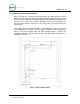
Figure 5. Portal Base Dimensions ......................................................................................... 5
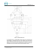
Figure 6. Base Installed in Concrete Pad .............................................................................. 8
Figure 7. Bricked-In Mounting Options ................................................................................ 10
Figure 8. Positioning the Adaptor Plate ............................................................................... 11
Figure 9. Door Positioning Options...................................................................................... 12
Figure 10. Portal Mounting for Bricked-In Installation......................................................... 13
Figure 11. Portal Brick-In with Adaptor Plate...................................................................... 14
Figure 12. Portal Brick-In with Adaptor Plate on Base Frame ............................................15
Figure 13. Portal Interior ..................................................................................................... 18
Figure 14. Inside the AC Connector.................................................................................... 19
Figure 15. Line - Neutral - Ground Connections................................................................. 19
Figure 16. Network Port Location ....................................................................................... 20
Figure 17. 2-Port Telephone Line Splitter........................................................................... 21
Figure 18. Telephone Line Connection (for Data Modem)................................................... 22
Figure 19. Wash I/O Board Connectors.............................................................................. 24
Figure 20. 10-Pin Phoenix Connector................................................................................. 24
Figure 21. 6-Pin Phoenix Connector................................................................................... 26
Figure 22. Intercom Component Locations on the Display IO Board.................................. 28
Figure 23. Four-Wire Intercom Configuration .....................................................................29
Figure 24. Three-Wire Intercom Configuration ....................................................................29
Figure 25. Two-Wire Intercom Configuration....................................................................... 29
Figure 26. BNC Male Plug for Camera Connection............................................................. 30