
User Manual


PORTAL TI
Site Planning and Base Installation for Portal TI Units 1
Document #: PTL1008
1 Site Planning and Prepara tion
1.1 General
This chapter provides guidelines for planning the Portal installation and preparing the
site. Site preparation includes:
• Determining how and where the Porta l will be mounted
• Installing conduit runs and required wiring
Note:
These instruction s serve as general gui delines only. If your wa sh manufacturer’s
installation requirem ents differ f rom these guideli nes, always meet th e wash
manufacturer’s requirements first.
Requirement s specified in local electrical and b uilding codes mu st be followed and
shall take precede nce over the guideline s provided within thi s document.
1.2 Mounting Options
Unitec offers a mounting base for the Portal and a “brick-in” kit. The ba se is availab le
in (2) heights, 35 in. for a standard (grade) mount and 29 in. for curb mounting. The
base consists of a tubular steel frame with a plastic cover. The frame is designed to
be embedded in a concrete pad and as such should be installed when concrete is
poured at the site. In cases where the con crete is alre ady in place, it’s recommended
that holes be drilled into the concrete to secure the legs of the base frame. Refer to
section
2.3 for base installation instructions.
The brick-in option includes an adaptor plate that’s designed to provide the proper air
circulation required for th e heat exch a nger air intake and exhaust. T he ada ptor plate
can be attached directly to the brick structure or to the top of a curb height base
frame. Refer to section 2. 4 for instructions on use of the brick-in adapter plate.
1.3 Positioning the P ortal
1.3.1 In-Bay Applications
For in-bay automatics and other applications where the Portal is installed at the wash
entrance, it should be placed 10’-14’ from the wash to ensure the proper timing and
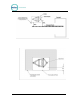
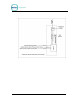
flow of customers. In applications where the Portal is installed adjacent to a
conveyor, it should be located 18“ from the centerline of the conveyor track. To
achieve this dimension, the Portal base frame should be located 26 in. from the
conveyor centerline as shown in
Figure 1.