Site Planning and Base Installation Guidelines for Portal TI Unitec 443-561-1200 • www.StartwithUnitec.
P O R T A L SITE PLANNING AND BASE INSTALLATION GUIDELINES FOR PORTAL TI This manual provides comprehensive site planning and base installation procedures for the Portal TI. If further assistance is needed, please contact the distributor from which the Portal TI was purchased.
P O R T A L T I Table of Contents 1 Site Planning and Preparation...................................................................................................... 1 1.1 General.................................................................................................................................. 1 1.2 Mounting Options .................................................................................................................. 1 1.3 Positioning the Portal .........................
P O R T A L T I Index of Figures Figure 1. Portal Installation at the Wash Entrance ..........................................................................2 Figure 2. Frame Location for Curb Mount .......................................................................................2 Figure 3. Express Exterior Island ....................................................................................................3 Figure 4. Conduit Runs...............................................................
P O R T A L T I 1 Site Planning and Preparation 1.1 General This chapter provides guidelines for planning the Portal installation and preparing the site. Site preparation includes: • Determining how and where the Portal will be mounted • Installing conduit runs and required wiring Note: These instructions serve as general guidelines only. If your wash manufacturer’s installation requirements differ from these guidelines, always meet the wash manufacturer’s requirements first.
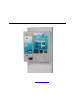
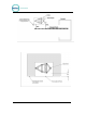
P O R T A L T I Figure 1. Portal Installation at the Wash Entrance For curb mount applications, the front surface of the Portal should be even with the edge of the curb. To achieve this dimension, the base frame should be installed so its leading edge is 8 in. from the edge of the curb as shown in Figure 2. Figure 2. Frame Location for Curb Mount 1.3.2 Express Wash Applications Express Exterior sites should be designed to provide 9 ft. wide traffic lanes at the Portals.
P O R T A L T I gate and tunnel entrance (referred to as the merge loop) to properly manage the vehicle queue. If the Unitec ReachFree ID (RFID) option is included, the RF Antenna should be located adjacent to the Portal. Figure 3 provides guidelines for the design of an Express lane with the Portal, gate and RFID (antenna) option. Refer to the installation instructions provided with the gate and RFID option for guidance in installing these devices. Figure 3. Express Exterior Island 1.
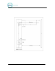
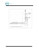
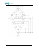
P O R T A L T I the quantity and gauge of wires to be installed. Refer to local and national electrical codes to select the proper conduit type and size. Figure 4 provides guidelines for conduit planning. Figure 4. Conduit Runs To ensure the conduit sections will be located within the Portal base and not interfere with the base frame, they should be routed so the stubs can be contained within the 4 inch square areas shown in the Figure 5.
P O R T A L T I Figure 5. Portal Base Dimensions The Portal base frame is a welded tubular structure that has the same plate on the top and bottom. Its designed so that wires and/or conduit can be routed into the Portal through the round conduit holes on the top. However, it will be far easier to bring the conduit stubs into the frame through the large rectangular cut outs on the bottom plate.
P O R T A L 1.4.2 T I Power Requirements The Portal requires 120 VAC, 8 Amps service. In applications where barrier gates are to be used, each gate requires 120 VAC, 5 Amps service. The Portal and Gate must be powered from separate circuits. Note: 1.4.3 Ensure the protective earth ground wires do not carry any motor return current. Only the neutral wire should carry return current. Follow local electrical code when wiring the Portal TI.
P O R T A L T I 2 Mechanical Installation 2.1 Hardware Required Prior to beginning the installation, take the time to verify that all the following required parts are present and accounted for.
P O R T A L T I 2.3 Base Installation Note: Pull all wires through conduits before mounting the base. See Electrical Planning for wiring requirements. When installing the Portal TI frame, it is recommended that the concrete pad be undercut, as illustrated in the figure below. This type of installation provides greater security. The undercut pad size should have the following dimensions: Pad Dimension Requirements Minimum Surface Width Undercut Depth Recommended 18” 48” 8” 24” Figure 6.
P O R T A L Note: T I For added security, the base can be filled with concrete. Before doing so however, the electrical conduits should be extended to the top of the frame. A rope (or similar material) should be tied around the plastic cover to prevent it from expanding as concrete is poured. Before setting the Portal in place, ensure the field-installed wires are routed to a point where they can be accessed and pulled through the wiring holes on the bottom of the Portal.
P O R T A L T I Figure 7. Bricked-In Mounting Options 2.4.2 Positioning the Portal The adapter plate should be located so its front edge is recessed 4.50” from the front face of the brick structure (as shown in Figure 8). The adapter plate has (2) sets of mounting holes. One set is used to install the Portal so its front door will be flush with the brick. The other set is used to recess the door within the brick. These (2) mounting options and hole patterns are illustrated in Figure 9 and Figure 10..
P O R T A L Figure 8.
P O R T A L Figure 9.
P O R T A L T I Figure 10. Portal Mounting for Bricked-In Installation 2.4.3 Brick-in Guidelines 2.4.3.1 Using the Adapter Plate The recommended procedure when mounting the Adaptor Plate directly to the brick structure is as follows: 1. Build the brick enclosure up to 36” high (8 rows of bricks) from the pavement. 2. Fill the enclosure with concrete. 3. Sink the Adaptor Plate with Mounting Bolts into the wet concrete. Position the Adaptor Plate 4 ½” back from the front edge of the brick.
P O R T A L T I Figure 11. Portal Brick-In with Adaptor Plate 2.4.3.2 Using the Curb Height Frame Follow the base installation instructions in section 2.3 to set the base frame in the concrete. The adapter plate attaches to the (3) studs on top of the frame with ½” nuts and washers. Position the frame so the front of the adapter plate will be recessed 4.5” from the front face of the brick (as shown in Figure 12).
P O R T A L Figure 12.
P O R T A L [THIS PAGE INTENTIONALLY LEFT BLANK] Site Planning and Base Installation for Portal TI Units Document #: PTL1008 16 T I
P O R T A L Appendix A. Dimensional Schematic of the Portal TI Figure 25.
P O R T A L Site Planning and Base Installation for Portal TI Units Document #: PTL1008 18 T I