Portal TI Console Installation & Operations Manual Unitec 443-561-1200 • www.StartwithUnitec.
P O R T A L T I PORTAL TI CONSOLE INSTALLTION AND OPERATIONS MANUAL SOFTWARE VERSION 2.0.0.1 In this manual, we discuss in detail the components and operations of the Portal TI Console. If further assistance is needed, please contact the distributor from which the Portal TI Console was purchased. When calling for assistance, you must have the following information available: Portal TI Console Serial Number: Distributor Name: C O P Y R I G H T © 2012 Unitec, Incorporated. All rights reserved.
P O R T A L Table of Contents 1 Controller Console Overview ........................................................................................................1 1.1 Introduction ................................................................................................................................1 1.2 Console Hardware Overview .....................................................................................................1 2 Console Hardware Installation Procedures ...................
P O R T A L Index of Figures Figure 1. Console Connection Locations ......................................................................................... 2 Figure 2. Red Connection Failed Screen......................................................................................... 4 Figure 3. Router Test Successful..................................................................................................... 5 Figure 4. Router Test Failed ........................................................
P O R T A L T I 1 Controller Console Overview 1.1 Introduction The Portal TI Console provides compact local access to the Management Mode of the Portal TI Software. Unitec designed the console primarily to be used as a Point of Sale (POS) inside your convenience sore (C-Store) or your site office. In this role, your onsite employees use the console to sell washes, update House Accounts, and perform shift or daily closes.
P O R T A L T I 2 Console Hardware Installation Procedures Installation of the Console consists of connecting the Power Supply, the Receipt Printer, the Card Reader, and then connecting the Console to the network router. 2.1 Requirements The console requires the following items: • LAN - The Console can only be used if you have the Portal connected to a Local Area Network (LAN).
P O R T A L T I 2. Connect the other end of the Ethernet cable to the LAN/Router. 3. Connect the Power Supply to the Power Supply Port. 4. Plug in the power supply. 2.2.2 Printer Installation Procedure 5. Connect the 25-pin connector of the printer cable to the parallel port on the Console; secure using the side screws. 6. Connect the Centronics connector (other end of the cable) to the wide slot on bottom of the Receipt Printer; secure using the wire holders on the printer slot. 7.
P O R T A L T I 3 Console Configuration Procedures Now that the Console has been installed, you will need to configure it to communicate with your Portal TI. 3.1 Requirements In order to properly configure the Console, you will need the computer name of the Portal TI Unit. The name is displayed in the Status box on the Portal Maintenance Screen. 3.2 Console Configuration Procedures The following procedures should only be performed by qualified IT professionals. 1.
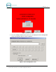
P O R T A L T I 3. Press the “Test Connection to Router Button” on the touch-screen to make sure the console can detect the router. 4. If router is detected, the following screen will appear: Figure 3. Router Test Successful 5. If the router is not detected, the following screen will appear: Check your router connections and perform the test again.
P O R T A L T I Figure 4. Router Test Failed 6. Press the Configure button on the touch-screen to display the Console Configuration screen. You may also press F1 on the keyboard. Figure 5.
P O R T A L T I 7. In the Computer Name field, replace the word PORTAL with the Computer Name of the Portal. 8. For example, if your Portal TI Computer Name is PORTAL94df4c, the Computer Name field should read PORTAL94df4c. 9. Click OK to continue. The Console Configuration screen allows you to configure the following settings: Computer Name – The name of the Portal the Console is connected to.
P O R T A L Figure 6.
P O R T A L T I 4 Console Operations The Portal console is designed to be used as a Point of Sale (POS) system inside the convenience store or office. The console allows you to sell wash codes, check and void codes sold from the register and gas pumps and print revenue or sales reports (must have a print server installed). In order to use the console, you must first configure the Sales screen through the Sierra Management Application pages.
P O R T A L T I 4.2 Daily Operations The previously configured sales screen will be displayed. Figure 7. Console Sales Screen From this screen, you simply select the wash package you wish to purchase or the report you wish to print.
P O R T A L T I Figure 8. Check-Void Code Screen To check or void a code, press the appropriate button on the sales screen. Enter the code. The console will display a message stating whether the code was either valid or invalid, or will disable the code. 4.3 Console Diagnostics The console software allows you to configure Console Settings and Touch-Screen Calibration, and to test the Printer and Card Reader.
P O R T A L T I Figure 9. Console Calibration Screen 4.3.2 Printer Test To test the receipt printer, press the F3 key on the keyboard. When you do, you will see the following screen: Figure 10. Console Printer Test Screen Click the Print button to test the printer.
P O R T A L T I 4.3.3 Card Reader Test To test the receipt printer, press the F4 key on the keyboard. When you do, you will see the following screen: Figure 11. Console Card Reader Test Screen Swipe a card to see the data being read by the card reader.
P O R T A L T I 5 Controller Console Maintenance The C-Store Controller Console is designed to require minimum maintenance. 5.1 Cleaning Clean the touch screen interface using non-abrasive cleaners. Spray the screen cleaner onto a soft, lint-free cloth, and then wipe the touch screen. Do not spray any cleaner directly onto the touch screen. 5.2 Verifying Ethernet Communications Next to the Ethernet port are two LEDs. When connected, at least one of the LEDs should be ON.
P O R T A L T I Figure 12. Lithium Battery Location 3. Remove and properly dispose of the old battery. 4. Insert the replacement battery. 5. Replace the top of the Console; be careful not to pinch any wires between the cover and the base. 6. Secure the top of the console to the base using the screws removed in Step 1.