
User Manual
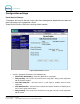


Document Number: GC1004 18
Document Title: Unitec CAME Gate and Gate Controller Installation Guide
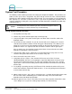
Gate Controller I/O Definitions
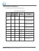
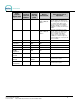
The following information is provided for troubleshooting purposes.
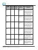
Table 1. Gate Controller I/O Definitions
Gate
Control
Signal name
Gate
Control
Terminal
Number
Gate
Control
PLC I/O
point
Device
Connection
Descriptive Use or
Operation
Lane 1
Request
21 X0 Input from Lane
1
Terminal at lane 1 will hold this line at
24VDC when a customer at Lane 1
has purchased a wash. Terminal will
remove signal when Lane 1 Hold
turns off.
Lane 2
Request
22 X1 Input from Lane
2
Terminal at lane 2 will hold this line at
24VDC when a customer at Lane 2
has purchased a wash. Terminal will
remove signal when Lane 1 Hold
turns off.
Lane 3
Request
23 X2 Input from Lane
3
Terminal at lane 3 will hold this line at
24VDC when a customer at Lane 31
has purchased a wash. Terminal will
remove signal when Lane 1 Hold
turns off.
Lane 4
Request
24 X3 Input from Lane4
Terminal at lane 4 will hold this line at
24VDC when a customer at Lane 4
has purchased a wash. Terminal will
remove signal when Lane 1 Hold
turns off.
Gate 1 Open 31 X4 Input from Gate
1 Lockout
24VDC is present on this line when
Gate for Lane 1 is Open or Opening
Gate 2 Open 32 X5 Input from Gate
2 Lockout
24VDC is present on this line when
Gate for Lane 2 is Open or Opening
Gate 3 Open 33 X6 Input from Gate
3 Lockout
24VDC is present on this line when
Gate for Lane 3 is Open or Opening
Gate 4 Open 34 X7 Input from Gate
4 Lockout
24VDC is present on this line when
Gate for Lane 4 is Open or Opening
Merge Loop 35 X10 Input from one or
more merge
Loops from
Gates 1-4
24VDC is present when any of the
merge loops from Gates 1-4 is active.
No gates will initiate an Open if a
Merge Loop is active.