Unitec CAME Gate and Gate Controller For Multi-Lane Applications Installation Guide Unitec www.StartwithUnitec.
UNITEC GATE CONTROLLER FOR MULTI-LANE APPLICATIONS INSTALLATION GUIDE This document provides comprehensive operational procedures for the Unitec Gate Controller. In this manual, we will discuss the setup, operation and maintenance of the Came gate and gate controller, which is only used in multi-lane applications. If further assistance is needed, please contact the distributor from which the product was purchased.
Table of Contents Introduction ...........................................................................................................................................1 Site Planning .........................................................................................................................................1 Electrical Planning ................................................................................................................................3 Power Requirements ..................
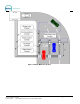
Index of Figures Figure 1. Example Multi-Lane Site Plan........................................................................................................ 2 Figure 2. Gate Reset Loop Dimensions........................................................................................................ 4 Figure 3. Multi-Lane Merge Loop Placement................................................................................................ 5 Figure 4. Wire the AC Power to the Gate Controller.................
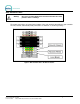
Introduction This document provides instructions for installing the Unitec gate controller for use with the Sentinel, Portal or WashSelect II entry units and Unitec supplied gates. Topics covered in this manual include: • • • Conduit and wiring requirements for the gate controller and gates Guidelines for locating and installing vehicle detection loops (required for safe gate operation) Connection schematics for the gate and gate controller wiring.
Figure 1.
Electrical Planning Power Requirements Each barrier gate requires a 115-120 VAC on a 5-Amp dedicated breaker, which should be provided during wash construction. Most installers will have power supplied directly from one of the three phases used to power the wash motors and controllers. If this method is used, special attention should be given to proper grounding at the unit, as well as in the breaker panel.
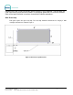
would only be used in new construction (where concrete is not yet poured). Saw cut loops are used in pre-existing concrete and installed in a rectangular groove that is cut into the concrete. Refer to the loop installation instructions for detailed installation procedures. Gate Reset Loop Each gate requires one gate reset loop. The reset loop should be formed into a 6’ long by 3’ wide rectangle and located as shown in Figure 2. Figure 2.
Merge Loops Merge loops are recommended to prevent vehicle queuing errors. These loops prevent a gate from opening until all paid vehicles have merged into a single line at the tunnel entrance. The number and size of loops required depends on the size of the merge zone area. The loop detector in each gate has can accommodate (1) merge loop so the maximum number of merge loops can not exceed the number of gates installed.
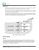
Gate Controller Power Warning: Disconnect 115VAC-120VAC power from the main power lines at the panel box before continuing! The power connections are located at the bottom of the main terminal strip within the gate controller. The Line, Neutral, and Ground (Earth) connections are labeled L, N, and E respectively. Figure 4.
Gate Power Figure 5. Gate Power Connect the hot and neutral line to the red phoenix connector at the top of the gate, according the installation manual included with the gate. Connect the ground wire to the cable lug on the base plate.
Gate to Gate Controller Wiring Figure 6. Came Gate to Gate Controller Connections There are 3 control wires that run from the gate to the gate controller. The gate reset loop and merge loop wiring (if applicable) is also illustrated, above. You must remove the loop detector block to access the block base for connecting the loop wires. The connections for each gate to the gate controller are illustrated on the left sides of Figures 7 and 8.
Figure 7.
Figure 8.
Configuration settings Portal/Sentinel Settings To configure the Portal or Sentinel, login to the Sierra Management Application then follow this path to navigate to the configuration screen: Setup>Device Profiles>(Edit next to device)>Wash Interface Figure 9. Wash Interface Screen 1. Enter the appropriate information in the following fields: • Wash-in-Use Handshaking – Select this option when using a gate.
• Start Button (over conveyor) – Used for Tunnel applications. This needs to be “off” if an entry gate is being used in conjunction with the Portal. Click OK to save your changes and return to the Bay Setup screen. Wash Select II Settings Before a Wash Select II (WSII) unit will operate with the Gate Controller, some configuration settings on the Wash Select II must be changed. Refer to the WSII Operations Manual, Section 2.8.8: Wash Interface Settings Tunnel mode for more information.
Depending on the interface of your WSII to the tunnel controller, you may need to put the WSII into “Attended Tunnel Mode” When the Tunnel Mode is set to “Attended,” each customer will receive a receipt to give to the attendant, who will then arm the appropriate wash. For an interface to a Gate controller, you should either use Roll Over or Attended mode. Do not use Mode 1 - Unattended mode. 1.
System Test Procedure The following section contains procedures for verifying the completed installation. The procedures are written to cover up to 4 lanes of operation. Any lanes that do not have the wires connected will be ignored by the Gate controller and do not need to be tested. The test procedure is to be performed in lane sequence (i.e., test Lane 1, then Lane 2, etc.).
11. If you have connected the wash arming signals to your Tunnel controller, you should verify a wash has been queued. If not, verify these connections. Testing for Lane 1 is complete. Testing System Interface for Lane 2 1. Remove any vehicles below all gate loops and merge loop. 2. Verify that all Gates have power and the gates are down. Gates should be switched to Automatic mode. 3. Verify the “Wash In Use” LED is lit at the entry unit. If not, check the wiring from Y1/Terminals 42 and 11 to entry unit.
6. If everything is operating correctly, X6 LED on the PLC should be lit and the LCD screen on the Gate controller should show “Wait for Gate 3”. If not, verify wiring from X6/Terminal 33 to the Gate terminal strip. 7. With the Gate for lane 3 open, drive a car through Lane 3. Validate that the Gate lowers after the rear of the vehicle comfortably passes off the Gate Loop. 8.
[THIS PAGE INTENTIONALLY LEFT BLANK] Document Number: GC1004 Document Title: Unitec CAME Gate and Gate Controller Installation Guide 17
Gate Controller I/O Definitions The following information is provided for troubleshooting purposes. Table 1. Gate Controller I/O Definitions Gate Control Signal name Gate Control Terminal Number Gate Control PLC I/O point Device Connection Descriptive Use or Operation Lane 1 Request 21 X0 Input from Lane 1 Terminal at lane 1 will hold this line at 24VDC when a customer at Lane 1 has purchased a wash. Terminal will remove signal when Lane 1 Hold turns off.
Gate Control Signal name Gate Control Terminal Number Gate Control PLC I/O point Device Connection Descriptive Use or Operation Lane 1 Wash in Use 41 Y0 Output to Wash in use signal for Lane 1 24VDC- is present when Gate Controller is commanding Terminal at Lane 1 to hold its current customer. Signal turns off when Terminal is to send customer through and fire wash into queue. Note: This is a sinking output. When testing, reference from terminal 11(RED) to Y0.
Gate Control Signal name Gate Control Terminal Number Gate Control PLC I/O point Device Connection Descriptive Use or Operation Open Gate 3 53 Y6 Output to Vend Input of Gate at Lane 3 Tied to the Vend input of the Gate, This line will become 24VDC when Gate 3is triggered to open. Note: This is a sinking output. When testing, reference from terminal 11(RED) to Y6.