C-Start Installation Manual Unitec 443-561-1200 • www.StartwithUnitec.
C - S T A R T C-START INSTALLATION MANUAL This manual provides installation instructions for the C-Start. It includes site planning, site preparation, the mechanical installation of the C-Start and the electrical wiring of the unit.
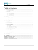
C - S T A R T Table of Contents 1 2 3 Site Planning and Preparation ......................................................................................................1 1.1 Positioning the C-Start...........................................................................................................2 1.2 Electrical ................................................................................................................................3 1.2.1 Power Requirements...........................
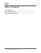
C - S T A R T Index of Figures Figure 1. C-Start Position................................................................................................................. 2 Figure 2. Conduit Runs .................................................................................................................... 4 Figure 3. Straight Bases Dimensions............................................................................................... 6 Figure 4. C-Start Interior Connections ........................
C - S T A R T 1 Site Planning and Preparation This chapter provides guidelines for positioning the C-Start and preparing the site. Site preparation includes: • Determining how and where the C-Start will be mounted • Installing conduit runs and required wiring These instructions serve as general guidelines only. If your wash manufacturer’s installation requirements differ from these guidelines, always meet the wash manufacturer’s requirements first.
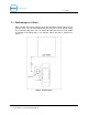
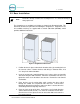
C - S T A R T 1.1 Positioning the C-Start When installed at the wash entrance, the C-Start should be located at least 12 feet from the wash. For curb mount applications, the front surface of the C-Start should be even with the edge of the curb. To achieve this dimension, the base frame should be installed so its leading edge is 7 in. from the edge of the curb as shown in the figure 1. Figure 1.
C - S T A R T 1.2 Electrical 1.2.1 Power Requirements C-Start requires 120 VAC, 8 Amps service with a dedicated circuit breaker. Note: Ensure the protective earth ground wires do not carry any motor return current. Only the neutral wire should carry return current. Follow local electrical code when wiring the C-Start. 1.2.
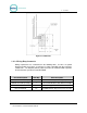
C - S T A R T Figure 2. Conduit Runs 1.2.3 Wiring Requirements Wiring requirements are summarized in the following table. As wires are pulled through conduit, ensure there is at least 6 ft. of wire extending from the end of the conduit stub. The Network (CAT-5) cable will need to be terminated with 8 position RJ-45 connectors per Ethernet standard 568B. Circuit Description Wire Qty Wire Description Power (115-120 VAC, 8 Amps).
C - S T A R T 2 Installation 2.1 Installation Hardware Prior to beginning the installation, take the time to verify that all the following required parts are present and accounted for. • Key set for door • Allen Wrench For Door • (4) Bolts and washers to secure the C -Start terminal to its mounting base.
C - S T A R T 2.3 Base Installation Note: Pull all wires through conduits before mounting the base. See Electrical Planning for wiring requirements. The C-Start bases are available in (2) heights as shown in the illustration below. This document describes the procedure for installing the straight base. Angled bases are also available and they are supplied with a manual addendum (MN1001), which provides additional instructions. Figure 3. Straight Bases Dimensions 1.
C - S T A R T 2.4 Mounting the C-Start 1. Rest the C-Start enclosure on top of the base and feed the wires through the rectangular opening in the bottom the enclosure. This opening is partially covered by a metal plate which can be slid forward or removed completely to provide greater access. 2. Align the (4) mounting holes on the bottom of the enclosure with the threaded inserts on the top of the base. Secure the enclosure to the base with the (4) bolts and washers supplied with the C-Start unit.
C - S T A R T 3.2 Connecting Power 1. Route the main power wires to the AC terminal strip on C-Start’s power panel (as shown below) and trim the wire to remove excess. Strip the insulation approximately ¼ ” on each conductor. 2. Remove the plastic shield on the power terminal block and loosen the 3 screws where the wires are to be connected.
C - S T A R T 3.3 Wash Control Wiring 3.3.1 Overview In applications where the C-Start will communicate with the Wash Controller, the wash control wires will need to be connected to the Wash I/O Board. This board is located on the right wall of the enclosure and is shown in the picture below. The board is supplied with screw terminal plugs (not shown) installed in the green connectors to accommodate field wiring. You will need a thin tipped, flat head screwdriver to open and tighten the screw terminals.
C - S T A R T 3.3.2 Wiring the Wash Relay Interface To wire the wash relays, remove the screw terminal plug from the J17 connector and install the wires from the PLC to the appropriate pin numbers per the table below. Replace the plug in J17 when finished. Table 1. Wash Relays Pin Signal Pin 1 Wash Output #1 Pin 2 Wash Output #2 Pin 3 Wash Output #3 Pin 4 Wash Output #4 Pins 5-8 Spare Option Relays (Outputs 5-8 respectively) Pin 9 Wash Relay Common Pin 10 N/A 3.3.
C - S T A R T Note: Wash equipment wiring may vary, and not all equipment manufacturers use the washfault interface. Refer to the manufacturer’s documentation for additional information. Table 2. Wash-In-Use Connections Pin Signal Pin 1 Wash-In-Use Hot Pin 2 Wash-In-Use Neutral Pin 3 Wash-Fault-Hot Pin 4 Wash-Fault-Neutral Pin 5 Wash-Complete-Hot Pin 6 Wash-Complete-Neutral 3.4 Network Cable Connection The Cat 5 cable will need to be terminated at each end with an RJ-45 modular plug.
C - S T A R T intercom wiring is sharing conduit with other communications wiring, but not required. Unitec does not supply intercom systems. 3.5.2 Intercom Connections The Intercom has two connectors which control the way in which the intercom is wired and the mode of operation. J17 is the interface and connects to the customer’s intercom unit. J23 is used to select mode of operation (two, three, or four wire intercom systems). Twisted pair / fully shielded cable is recommended for optimum performance.
C - S T A R T 4 System Startup For fully detailed instructions, please see the Sierra Management Application Programming Manual on the www.StartwithUnitec.com website. 1. Power up the C-Start. 2. Using a laptop, login into the Sierra Management System. 3. Enter the Site information and credit networking information, wash information, and setup a device profile. 4. Download the device profile. 5. The C-Start will reboot and be in full operational mode.
C - S T A R T [ T H I S P A G E I N T E N T I O N A L L Y Document Number: CST1001 Document Name: C-Start Installation Manual L E F T B L A N K ] 14
C - S T A R T Appendix A - POS Interface Option The external POS option allows wash codes to be purchased at Point of Sale (POS registers or gas pumps. This option includes a port conversion device, which connects between the Unitec router and the C-store POS System. A 3ft Ethernet cable is included for connecting the Ethernet port of the converter to the Unitec router (see Appendix B).
C - S T A R T Appendix B - C-Start Networking Unitec supplies a pre-programmed router for connecting devices as a local network. The networked devices will vary based on options ordered and may include: • One or more C-Start units • A C-Start Console • A POS Interface device (to communicate with a C-store POS System) • A print server (for connecting a local report printer) In cases where there will be more than (4) Unitec devices on the network, an Ethernet switch will need to be added.
C - S T A R T Third party devices should not be connected directly to the Unitec router. The broadband device supplied for Internet service (e.g. DSL or Cable modem) will often have a built-in router that can be used to connect these devices. In some cases however, a separate router will need to be installed between the broadband modem and the Unitec router. The following illustration shows the use of a 2nd router for 3rd party device connections.
C - S T A R T Appendix C – Terminating Ethernet Cables 1. Carefully remove the outer jacket of the cable. Be careful when stripping the jacket as to not nick or cut the internal wiring. One good way to do this is to cut lengthwise with snips or a knife along the side of the cable, away from yourself, about an inch toward the open end. This reduces the risk of nicking the wires' insulation.
C - S T A R T 4. Arrange the wires in the following order (from left to right): • • • • • • • • white/orange orange white/green blue white/blue green white/brown brown 5. Press all the wires flat and parallel between your thumb and forefinger. Verify the colors have remained in the correct order. Cut the top of the wires even with one another so that they are 1/2" (12.
C - S T A R T 7. Place the wired plug into the crimping tool. Give the handle a firm squeeze. You should hear a ratcheting noise as you continue. Once you have completed the crimp, the handle will reset to the open position. To ensure all pins are set, some prefer to double-crimp by repeating this step. 8. Repeat all of the above steps with the other end of the cable. Test the cable to ensure that it will function in the field. Mis-wired and incomplete network cables could lead to headaches down the road.