
Installation manual

29
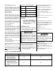
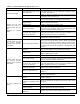
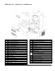
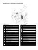
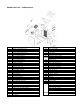
REPAIR PART LIST – P3LBX12F08001A & P3LBX14F12001A
ITEM DESCRIPTION
1 Panel Assembly, Left Side (Tan)
2 Panel Assembly, Right Side (Tan)
3 Panel, Upper Rear (Tan)
4 Panel Assembly, Blower Division
5 Panel Assembly, Base
6 Panel, Inner Front
7 Door, Blower Access (Tan)
7A Handle, Door
8 Panel, Front Door (Tan)
8A Bezel, Logo
8B Label, Logo
9 Panel, Top (Tan)
10 Heat Exchanger Assembly
11 Bracket Assembly, Firepot
12 Chamber, Replacement Combustion
13 Baffle, Rear
14 Panel Baffle, Left Side
15 Panel Baffle, Right Side
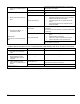
16 Mounting Plate Assy., Oil Burner
16A Gasket, Inspection Door (RH)
16B Gasket, Inspection Door (LH)
16C Gasket, Inspection Door (Center)
17 Gasket, Pouch
18 Gasket, Clean-Out Cover (Flue Pipe)
19 Collar, Flue Pipe (2 Req’d)
20 Cover, Clean-Out
21 Gasket, Clean-out Cover
Filter, Air (20 x 20 x 1, Permanent)
22
Filter, Air (20 x 25 x 1, Permanent)
23 Panel, Control
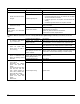
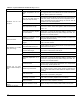
ITEM DESCRIPTION
24 Cover, Control Panel
25 Wire Harness, Blower Direct Drive
26 Wire Harness, Fan Timer Board
27 Wire Harness, Transformer and Supply
28
29 Board, Fan Timer
30 Transformer
Limit Control (BOF, 140
o
F)
31
Limit Control (BOF, 160
o
F)
32
33 Regulator, Draft (5”)
34 Burner, Oil
34A Motor, Oil Burner
34B Pump, Oil, (Cleancut)
34C Igitor, Solid State
34D Control, Primary Combustion
34E Tube Combination, Air
34F Retention Head, Flame
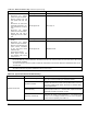
Nozzle (0.70 gph/70
o
W
34G
Nozzle (1.00 gph/70
o
W
35 Blower Assembly, Complete
35A Housing, Blower and Wheel
35B Wheel, Blower
35C Motor, Blower
35D Mount Arms, Motor (3 Req’d)
35E Run Capacitor, Motor (10MFD/370VAC)
35F Strap, Capacitor
35G Blower Feet (LH)
35H Blower Feet (RH)