
Installation manual

28
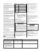
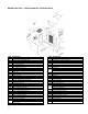
REPAIR PART LIST – P3HMX14F10001 & P3HMX20F12001
ITEM DESCRIPTION
1 Assembly. Left Side Panel (Tan)
2 Assembly, Right Side Panel (Tan)
3 Assembly, Rear Panel (Tan)
4 Assembly, Blower Division Panel
5 Base Panel Assembly
6
7 Inner Front Panel Assembly
7A Primary Limit Control (180
o
) (Upper)
7B Primary Limit Control (180
o
) (Lower)
8 Blower Access Door (Tan)
8A Door Handle
9 Front Door Panel (Tan)
10 Top Panel (Tan)
11 Heat Exchanger Assembly
12 Firepot Bracket Assembly
13 Replacement Combustion Chamber
14 Rear Panel Baffle
14A Left Side Panel Baffle
14B Right Side Panel Baffle
15 Oil Burner Mounting Plate Assembly
15A Gasket, Inspection Door (RH)
15B Gasket, Inspection Door (LH)
15C Gasket, Inspection Door (Center)
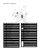
16 Gasket, Pouch
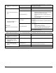
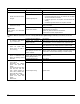
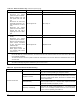
ITEM DESCRIPTION
16A Gasket, Flue Pipe
17 Gasket, Clean-out Cover (2 Req’d)
18 Retainer, Clean-out Gasket (2 Req’d)
19 Cover, Clean-out (2 Req’d)
20 Frame, Filter
20A Filter Frame End Support
21 Filter, Air (16 x 25 x 1 Permanent)
22 Box, Junction
22A Cover, Junction Box
23 Blower Housing and Wheel
24 Blower Wheel
25 Motor, Blower
26 Motor Mount Band
26A Motor Mount Arms (3 Req’d)
Capacitor, Blower Motor (10MFD)
26B
Capacitor, Blower Motor (20MFD)
26C Capacitor Strap
26D Capacitor Insulator
26E Blower Side Rails (2 Req’d)
26F Wire Harness, Blower Motor
26G Wire Harness, Fan Timer Board
26I Wire Harness, Transformer
26J Wire Harness, Supply
26K Wire Harness, Limit to Limit