
Unit installation


247585-UAI-A-0706
Unitary Products Group 5
TWO STAGE GAS VALVE MODELS
TWO STAGE GAS VALVE MODELSTWO STAGE GAS VALVE MODELS
TWO STAGE GAS VALVE MODELS
NOTE:
The regulated outlet pressures, both low and high,
have been calibrated at the factory. Additional pressure
adjustment should not be necessary. If adjustment is neces-
sary, set to the following specifications. After adjustment,
check for gas leakage.
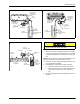
1. Refer to Figure 2 for location of pressure regulator
adjustment cap and adjustment screws on main gas
valve.
2. Turn gas and electrical supplies on and follow the oper-
ating instructions to place the unit back in operation.
3. Adjust manifold pressure by adjusting gas valve regula-
tor screw for the appropriate gas per the following:
:
IMPORTANT -
If gas valve regulator is turned in (clockwise),
manifold pressure is increased. If screw is turned out (coun-
terclockwise), manifold pressure will decrease.
4. After the manifold pressure has been adjusted, re-calcu-
late the furnace input to make sure you have not
exceeded the specified input on the rating plate. Refer to
“CALCULATING THE FURNACE INPUT (NATURAL
GAS)”. Refer to calculations on Page 6.
5. Once the correct BTU (kW) input has been established,
turn the gas valve to OFF and turn the electrical supply
switch to OFF; then remove the flexible tubing and fit-
tings from the gas valve pressure tap and the pressure
reference hose from the right side of the burner box and
tighten the pressure tap plug using the 3/32” (2.4 mm)
Allen wrench. Replace the burner box front cover (if it
was removed) and place the pressure reference hose
back on the gas valve.
6. Turn the electrical and gas supplies back on, and with
the burners in operation, check for gas leakage around
the gas valve pressure port for leakage using an
approved gas detector, a non-corrosive leak detection
fluid, or other leak detection methods.
CALCULATING THE FURNACE INPUT
CALCULATING THE FURNACE INPUTCALCULATING THE FURNACE INPUT
CALCULATING THE FURNACE INPUT
(NATURAL GAS)
(NATURAL GAS)(NATURAL GAS)
(NATURAL GAS)
NOTE:
Burner orifices are sized to provide proper input rate
using natural gas with a heating value of 1030 BTU/Ft
3
. If the
heating value of your gas is significantly different, it may be
necessary to replace the orifices.
1. Turn off all other gas appliances connected to the gas
meter.
2. At the gas meter, measure the time (with a stop watch) it
takes to use 2 cubic ft. (0.0566 m
3
) of gas.
3. Calculate the furnace input by using one of the following
equations.
CALCULATING THE FURNACE INPUT
CALCULATING THE FURNACE INPUTCALCULATING THE FURNACE INPUT
CALCULATING THE FURNACE INPUT
(PROPANE GAS)
(PROPANE GAS)(PROPANE GAS)
(PROPANE GAS)
NOTE:
Burner orifices are sized to provide the proper input
rate using propane gas with a heating value of 2500 BTU/Ft
3
.
If the heating value of your gas is significantly different, it may
be necessary to replace the orifices with different size ori-
fices. Follow the procedure below to calculate the furnace
input.
1. Turn off all gas appliances connected to the gas meter.
2. Start the furnace.
3. Use a stop watch to measure the time it takes for the fur-
nace to burn 1 cubic ft. of gas.
4. Calculate the furnace input by using one of the following
equations.
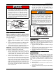
An overpressure protection device, such as a pres-
sure regulator, must be installed in the gas piping
system upstream of the furnace and must act to limit
the downstream pressure to the gas valve so it does
not exceed 0.5 PSI (14” w.c.) (3.48 kPa). Pressures
exceeding 0.5 PSI (14” w.c.) (3.48 kPa) at the gas
valve will cause damage to the gas valve, resulting
in a fire or explosion or cause damage to the furnace
or some of its components that will result in property
damage and loss of life.
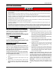
FIGURE 1 -
Single Stage Gas Valve
INLET
WRENCH
BOSS
INLET
PRESSURE
PORT
ON
OFF
ON/OFF SWITCH
(Shown in ON position)
MAIN REGULATOR
ADJUSTMENT
OUTLET
OUTLET
PRESSURE
PORT
VENT PORT
The manifold pressure must be checked with the
screw-off cap for the gas valve pressure regulator in
place. If not, the manifold pressure setting could
result in an over-fire condition. A high manifold
pressure will cause an over-fire condition, which
could cause premature heat exchanger failure. If
the manifold pressure is too low, sooting and even-
tual clogging of the heat exchanger could occur. Be
sure that gas valve regulator cap is in place and
burner box to gas valve pressure reference hose is
connected.
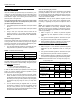
FIGURE 2 -
Two Stage Gas Valve
INLET
WRENCH
BOSS
INLET
PRESSURE
PORT
ON OFF
SWITCH
LOW STAGE REGULATOR
ADJUSTMENT
OUTLET
OUTLET
PRESSURE
PORT
VENT
PORT
HIGH STAGE REGULATOR
ADJUSTMENT