
Unit installation


247585-UAI-A-0706
4 Unitary Products Group
ADJUSTMENT OF MANIFOLD GAS PRESSURE
ADJUSTMENT OF MANIFOLD GAS PRESSUREADJUSTMENT OF MANIFOLD GAS PRESSURE
ADJUSTMENT OF MANIFOLD GAS PRESSURE
FOR 80% FURNACES
FOR 80% FURNACESFOR 80% FURNACES
FOR 80% FURNACES
Inlet and manifold gas pressure may be measured by con-
necting the “U” tube manometer to the gas valve with a piece
of tubing. Follow the appropriate section in the instructions
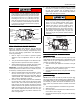
below. Refer to Figure 1 for a drawing of the locations of the
pressure ports on the gas valve.
Turn gas off at the ball valve or gas cock on gas supply
line before the gas valve. Find the pressure ports on the
gas valve marked Out P and In P.
1. The manifold pressure must be taken at the port marked
OUT P.
2. The gas line pressure must be taken at the port marked
IN P.
3. Using a 3/32” (2.4 mm) Allen wrench, loosen the set
screw by turning it 1 turn counter clockwise. DO NOT
REMOVE THE SET SCREW FROM THE PRESSURE
PORT.
Read the inlet gas pressure
Connect the positive side of the manometer to the IN P Tap
on the gas valve. Do not connect any tubing to the negative
side of the manometer, as it will reference atmospheric pres-
sure. Refer to Figure 1 for connection details.
1. Turn gas and electrical supplies on and follow the oper-
ating instructions to place the unit back in operation.
IMPORTANT - The inlet gas pressure operating range table
specifies what the minimum and maximum gas line pressures
must be for the furnace to operate safely. The gas line pres-
sure MUST BE a minimum of
• 7” W.C. (1.74 kPA) for Natural Gas
• 11” W.C. (2.74 kPA) for Propane (LP) Gas
in order to obtain the BTU input specified on the rating plate
and/or the nominal manifold pressure specified in these
instructions and on the rating plate.
2. Once the correct gas inlet pressure has been estab-
lished, see Table 13, turn the gas valve to OFF and turn
the electrical supply switch to OFF; then remove the flex-
ible tubing from the gas valve pressure tap and tighten
the pressure tap plug using the 3/32” (2.4 mm) allen
wrench.
3. Turn the electrical and gas supplies back on, and with
the burners in operation, check for gas leakage around
the gas valve pressure port for leakage using an
approved non-corrosive gas leak detection fluid, or other
non-flammable leak detection methods.
Read the manifold gas pressure
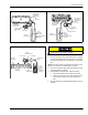
Connect the positive side of the manometer to the adapter
previously installed in the OUT P Tap on the gas valve. Do
not connect any tubing to the negative side of the manome-
ter, as it will reference atmospheric pressure. Refer to Figures
3 and 4 for connection details.
IMPORTANT - The cap for the pressure regulator must be
removed entirely to gain access to the adjustment screw.
Loosening or tightening the cap does not adjust the flow of
gas.
NOTE: The regulated outlet pressures, both low and high,
have been calibrated at the factory. Additional pressure
adjustment should not be necessary. If adjustment is neces-
sary, set to the following specifications. After adjustment,
check for gas leakage.
1. Refer to Figure 1 for location of pressure regulator
adjustment cap and adjustment screws on main gas
valve.
2. Turn gas and electrical supplies on and follow the oper-
ating instructions to place the unit back in operation.
3. Adjust manifold pressure by adjusting gas valve regula-
tor screw for the appropriate gas per the following:
SINGLE STAGE GAS VALVE MODELS
SINGLE STAGE GAS VALVE MODELSSINGLE STAGE GAS VALVE MODELS
SINGLE STAGE GAS VALVE MODELS
1. Refer to Figure 1 or 2 for location of pressure regulator
adjustment cap and adjustment screw on main gas
valve.
2. Turn gas and electrical supplies on and follow the oper-
ating instructions to place the unit back in operation.
3. Adjust manifold pressure by adjusting gas valve regula-
tor screw for the appropriate gas per the following table.
TABLE 1:
Inlet Gas Pressure Range
INLET GAS PRESSURE RANGE
Natural Gas Propane (LP)
Minimum 4.5” W.C. (1.12 kPa) 8.0” W.C. (1.99 kPa)
Maximum 10.5” W.C. (2.61 kPa) 13.0” (3.24 kPa) W.C.
TABLE 2:
Nominal Manifold Pressure -Two Stage Valve (High Fire)
or Single Stage Valve
SINGLE/SECOND STAGE MANIFOLD PRESSURES (IN WC)
Altitude (feet)
0-7999 8000-8999 9000-9999
Gas Heating Value
(BTU/cu ft.)
2500 (LP) 9.8 8.2 7.5
SINGLE/SECOND STAGE MANIFOLD PRESSURES (KPA)
Altitude (m)
0-2437 2438-2742 2743-3048
Gas Heating Value
(MJ/cu m)
93.2 (LP) 2.44 2.03 1.86
TABLE 3:
Nominal Manifold Pressure - Two Stage Valve (Low Fire)
FIRST STAGE MANIFOLD PRESSURES (IN WC)
Altitude (feet)
0-7999 8000-8999 9000-9999
Gas Heating Value
(BTU/cu ft.)
2500 (LP) 4.1 3.8 3.5
FIRST STAGE MANIFOLD PRESSURES (KPA)
Altitude (m)
0-2437 2438-2742 2743-3048
Gas Heating Value
(MJ/cu m)
93.2 (LP) 1.03 0.95 0.87