
Unit installation


247585-UAI-A-0706
2 Unitary Products Group
FURNACE CONVERSION
FURNACE CONVERSIONFURNACE CONVERSION
FURNACE CONVERSION
1. Shut off gas supply at shutoff valve upstream of the fur-
nace or at meter as required.
2. Disconnect gas supply piping from gas valve at furnace.
3. Remove the upper access door. On 90+AFUE units,
remove the burner box cover.
4. Carefully remove the wires from the gas valve and note
their location so they may be properly replaced. Remove
the screws that hold the manifold to the manifold brack-
ets and slide the manifold off the burners. On 90+ AFUE
units, the manifold is retained by two screws at the bot-
tom and hooks in at the top of the burner box.
5. Remove the main burner orifices from the manifold and
retain for future use.
6. Install the propane main burner orifices in the manifold
and tighten them. After installing a propane orifice in
each location, any leftover orifices may be discarded.
7. Reinstall the manifold in the assembly by reversing the
removal process.
8. Reconnect the wires to the proper terminals on the gas
valve.
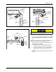
9. When installing gas piping on 80% AFUE units, insert
tapped gas pipe nipple (supplied with kit) into inlet fitting
of gas valve. If using the right side cabinet knock out, the
nipple can be either be installed before or after making
the u-bend. On 90% AFUE units, install a field provided
elbow into the inlet fitting on the gas valve and then
install the tapped gas pipe nipple.
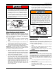
10. Install (thread) the gas line pressure switch (supplied
with kit) into the 1/8 NPT tapped hole in nipple applying
pipe dope to the switch fitting prior to installation. Tighten
the switch making sure the connection does not leak.
NOTE: The gas line pressure switch will cause the furnace to
lock out if the gas supply pressure drops below 6” w.c. The
ignition control will display a fault code 7 and will reset after
one hour.
11. Disconnect the purple wire from the flame sensor.
12. Using the wire harness (supplied with kit) connect the
purple wire from the flame sensor into the insulated male
connector; connect the two 1/4” insulated terminals to
the pressure switch; and connect the remaining insu-
lated terminal to the flame sensor.
13. Convert the gas valve for LP (propane) gas operation by
following the instructions and using the components sup-
plied in the envelope. Apply the label supplied in the kit
to the gas valve to show that it has been converted.
14. Reattach the manifold and orifices to the furnace, mak-
ing sure that the orifices are pointing properly down the
center of the burners.
15. Reconnect the electrical wires to the gas valve using the
wiring diagram as a guide
16. Reconnect the gas supply piping to the gas valve and
insure that all gas connections are tight.
17. Turn on gas supply to furnace and check all gas connec-
tions with suitable leak detector.
18. Install the propane gas conversion label as described in
the LABELS section of this instruction.
19. Refer to the unit installation instructions to complete the
installation before continuing with these procedures.
NOX SCREEN REMOVAL
NOX SCREEN REMOVAL NOX SCREEN REMOVAL
NOX SCREEN REMOVAL
(Lo-NOx Models Only)
(Lo-NOx Models Only)(Lo-NOx Models Only)
(Lo-NOx Models Only)
1. Make sure that the electrical power to the unit is turned
off and that the gas supply is turned off at the shutoff
valve.
2. Remove the blower compartment and burner compart-
ment access doors.
3. Disconnect the gas supply piping at the union to permit
removal of the entire burner and gas control assembly
from the vestibule panel. Use the wrench boss on the
gas valve when removing or installing this piping.
4. Unplug the ignitor from the wire harness. Disconnect the
flame sensor wires located on top of the air shield.
Unplug the gas valve from the wiring harness.
5. Remove the ignitor and ignitor bracket. Handle the igni-
tor very carefully since it is fragile and easily broken.
6. Remove the screws holding the burner assembly to the
vestibule panel. It may be necessary to remove the roll-
out switch bracket(s) to gain access to one or more of
these screws.
7. Remove the burner assembly. It should be possible to
swing the burner assembly out of the way without dis-
connecting the remaining wires.
8. With the burner assembly out of the way, simply slide the
NOx screens out of the heat exchanger tubes and dis-
card the screens.
9. Replace all components in reverse order. Reconnect all
wiring.
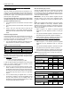
CONTENTS OF KIT
DESCRIPTION PART NUMBER QTY
Gas Line Pressure Switch 17471 1
Tapped Gas Pipe Nipple 18095 1
Propane Gas Orifice 18081 7
Wire Harness 20461 1
Installation Instructions 247585 1
Valve Conversion Kit 7614 1
(WR #92-0923)
Packaging Kit (33 Cu In) 93689 1
Label, Bar Code 11931 1
Label, Conversion 255424 1
Label, Carton 255426 1
Label, Conversion Rating
Plate
255417 1
An overpressure protection device, such as a pres-
sure regulator, which conforms to the National Fuel
Gas code, ANSI Z223.1 (U.S.) or CAN-B149.1 or.2
(Canada) and acts to limit the downstream pressure
to value that does not exceed 0.5 PSI (14" w.c.),
must be installed in the gas piping system upstream
of the furnace. Failure to do so may result in a fire or
explosion or cause damage to the furnace or some
of its components.
The gas supply shall be shut off prior to disconnect-
ing the electrical power, before proceeding with the
conversion.