
Operating instructions

Unitary Products Group 5
035-17452-000 Rev. B (0106)
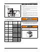
INSTALLATION OF CHIMNEY KIT ASSEMBLY
The Tile Lined Chimney Kit is for use on Furnace Models
listed on Page 2.
1. Disconnect power and shut off the gas supply to the fur-
nace.
2. Turn off gas supply to the furnace at the manual valve.
3. Remove burner access door.
4. Remove screw from the front of the chimney kit. Set the
screw aside.
5. Attach the chimney kit onto the flue outlet of the furnace.
6. Secure the chimney kit to the furnace with the screw that
was set aside.
7. Install the black bushing that is provided in the parts bag
of the kit into one of the 7/8” diameter holes located on
the side of the furnace.
8. Route the wire harness from the chimney kit into the
burner compartment of the furnace through the bushing.
For counterflow furnaces, route the wire through the
Dgrommet and then into the burner compartment.
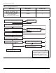
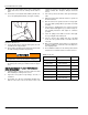
FIGURE 3: Multiple Appliance Vent Connector
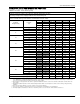
TABLE 4: Masonry Chimney Liner Dimensions
with Circular Equivalents
Nominal
Liner
Size
(Inches)
Inside Diameter
of Liner
(Inches)
Inside Diameter
or Equivalent
Diameter
(Inches)
Equivalent
Area
(Square
Inches)
4 x 8 2 1/2 x 6 1/2
412.2
519.6
628.3
738.3
8 x 8 6 3/4 x 6 3/4
7.4 42.7
850.3
8 x 12 6 1/2 x 10 1/2
963.6
10 78.5
12 x 12 9 3/4 x 9 3/4
10.4 83.3
11 95
12 x 16 9 1/2 x 13 1/2
11.8 107.5
12 113
14 153.9
16 x 16 13 1/4 x 13 1/4
14.5 162.9
15 176.7
16 x 20 13 x 17
16.2 206.10
18 254.4
20 x 20 16 3/4 x 16 3/4
18.2 260.2
20 314.10
H
D
D
A
R
R
CONNECTOR
RISE “R”
SINGLE WALL
OR TYPE “B” VENT
TYPE “B”
DOUBLE WALL
GAS VENT USED
AS CONNECTOR
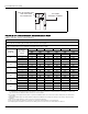
The wire harness to the kit shall not be routed into
the junction box.
The wire harness should be routed above the burner
box to avoid the possibility of any damage to the
wire. (See Figure 4 below).
FIGURE 4: Burner Box