
Installation manual


66832-UIM-D-1205
8 Unitary Products Group
RESIDENTIAL AND NON HUD MODULAR HOME
UPFLOW RETURN PLENUM CONNECTION
Return air may enter the furnace through the side(s) or bottom depend-
ing on the type of application. Return air may not be connected into the
rear panel of the unit. In order to achieve the airflow indicated, it is rec-
ommended those applications over 1800 CFM (57 m³/min) use return
air from two sides, one side and the bottom or bottom only. For single
return application, see data and notes on blower performance data
tables in this manual.
NOTE: The only return duct configurations that is approved for models
that have two separate fans are:
• Return duct attached to both sides of the furnace.
• Bottom and side return duct.
BOTTOM RETURN AND ATTIC INSTALLATIONS
Bottom return applications normally pull return air through a base plat-
form or return air plenum. Be sure the return platform structure or return
air plenum is suitable to support the weight of the furnace.
The return air ducts to the furnace must have a total cross sectional
area of not less than two square inches per 1000 BTUH of furnace input
rating for heating operation. If air conditioning is to be installed with the
furnace, larger return air ducts may be required, depending on the
capacity of the air conditioner and the airflow required. The return air
opening in the top of the furnace is large enough for the largest capacity
air conditioner for which the furnace blower is rated. The return air duct
or plenum can be connected to the furnace by performing the following
steps:
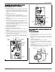
1. Bend the 3/4" flanges that will be used to attach the return air ple-
num using the scribe marks in the furnace base. Refer to Figure 5
for flange locations.
2. Be sure to seal the furnace to plenum connections to prevent air
leakage. Refer to Figure 5 for unit and plenum dimensions. Attic
installations must meet all minimum clearances to combustibles
and have floor support with required service accessibility.
Attic installations must meet all minimum clearances to combustibles
and have floor support with required service accessibility.
FLOOR BASE AND DUCTWORK INSTALLATION
Downflow Combustible Floor Base
Installations on combustible material or floors must
use a combustible floor base shown in Figure 6. The
perforations in the wrapper flanges must be bent in
towards the heat exchanger to allow for the coil duct
flange to recess into the furnace Follow the instruc-
tions supplied with the combustible floor base acces-
sory. This combustible floor base can be replaced with
a matching cooling coil, properly sealed to prevent
leaks. Follow the instructions supplied with the cooling coil cabinet for
installing the cabinet to the duct connector. Refer to the installation
instructions for additional information.
Downflow Duct Connectors
All downflow installations must use a suitable duct connector approved
by the furnace manufacturer for use with this furnace. The duct connec-
tors are designed to be connected to the rectangular duct under the
floor and sealed. Refer to the instructions supplied with the duct con-
nector for proper installation. Refer to the separate accessory parts list
at the end of these instructions for the approved accessory duct con-
nectors.
When replacing an existing furnace, if the existing plenum is not the
same size as the new furnace then the existing plenum must be
removed and a new plenum installed that is the proper size for the new
furnace.
IMPORTANT: If an external mounted filter rack is being used see the
instructions provided with that accessory for proper hole cut size.
Downflow Air Conditioning Coil Cabinet
The furnace should be installed with coil cabinet part number specifi-
cally intended for downflow application. If a matching cooling coil is
used, it may be placed directly on the furnace outlet and sealed to pre-
vent leakage. For details of the coil cabinet dimensions and installation
requirements, refer to the installation instructions supplied with the coil
cabinet.
The perforations in the wrapper flanges must be bent away from the
heat exchanger to create duct flanges so the air conditioning coil can be
properly seated on the furnace. Attach the air conditioning coil cabinet
to the duct connector, and then position the furnace on top of the coil
cabinet. The connection to the furnace, air conditioning coil cabinet,
duct connector, and supply air duct must be sealed to prevent air leak-
age.
IMPORTANT: On all installations without a coil, a removable access
panel is recommended in the outlet duct such that smoke or reflected
light would be observable inside the casing to indicate the presence of
leaks in the heat exchanger. This access cover shall be attached in
such a manner as to prevent leaks.
RESIDENTIAL AND NON HUD MODULAR HOME
DOWNFLOW RETURN PLENUM CONNECTION
The return duct system must be connected to the furnace inlet and the
return duct system must terminate outside the space containing the fur-
nace. When replacing an existing furnace, if the existing plenum is not
the same size as the new furnace then the existing plenum must be
removed and a new plenum installed that is the proper size for the new
furnace.
Attach the return plenum to the furnace inlet duct flanges. This is typi-
cally through the use of “S” cleat material when a metal plenum is used.
The use of an approved flexible duct connector is recommended on all
installations. The connection of the plenum to the furnace and all the
ducts connecting to the plenum must be sealed to prevent air leakage.
The sheet metal should be crosshatched to eliminate any popping of
the sheet metal when the indoor fan is energized.
The duct system is a very important part of the installation. If the duct
system is improperly sized the furnace will not operate properly. The
ducts attached to the furnace must be of sufficient size so that the fur-
nace operates at the specified external static pressure and within the air
temperature rise specified on the nameplate.
IMPORTANT: If an external mounted filter rack is being used see the
instructions provided with that accessory for proper hole cut size.
HORIZONTAL MODELS
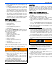
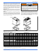
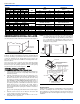
FIGURE 6: Combustible Floor Base Accessory
DOWNFLOW
FURNACE
WARM AIR PLENUM
WITH 1” FLANGES
FIBERGLASS
INSULATION
FIBERGLASS TAPE
UNDER FLANGE
COMBUSTIBLE FLOOR
BASE ACCESSORY