
Installation manual

66832-UIM-D-1205
Unitary Products Group 23
TOOLS AND INFORMATION THAT WILL BE
REQUIRED IN ORDER TO PROPERLY PERFORM THE
FURNACE STARTUP PROCEDURE.
1. Call the local gas supplier to obtain heating value of the natural
gas. If you cannot obtain the heating valve of the gas from the gas
supplier, you may use a default value of 1030 BTU/SCF (38.8 MJ /
m³).
2. You will need a thermometer or portable digital thermometer to
read the supply and return air temperatures.
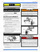
3. You will need a U-tube manometer or digital equipment that has
the ability to read pressures between 0 – 15” in.w.c (0 - 3.73 kPa)
in order to measure the gas line and the manifold pressures.
4. You will need a 3/32” Allen wrench for the pressure port plugs in
the gas valve.
5. You will need 2 pieces of 1/8” (0.3 cm) ID flexible tubing that is 12”
(30 cm) in length, 2 – pieces of 1/8” (0.3 cm) tubing that are 4”
(10.0 cm) in length, a 1/8” (0.3 cm) tee and a 1/8” (0.3 cm) adapter
to connect the U-tube manometer or the digital pressure measur-
ing equipment to the gas valve pressure ports.
There is an accessory kit (1PK0601) available from Source 1, which
has the following items:
• 1 - 12” (30 cm) length x 1/8” (0.3 cm) diameter tubing
• 2 – pieces of 4” (10 cm) length x 1/8” (0.3 cm) diameter tubing
• 1 - 5/16” (0.8 cm) tee
• 1 – 5/16” (0.8 cm) x 1/8” (0.3 cm) reducing coupling
• 1 – 1/8” (0.3 cm) adapter
There is a accessory kit (1PK0602) available from Source 1, which has
the following items:
• 12” (30 cm) length x 1/8” (0.3 cm) diameter tubing
• 2 – pieces of 4” (10 cm) length x 1/8” (0.3 cm) diameter tubing
• 1 - 5/16” (0.8 cm) tee
• 1 – 5/16” (0.8 cm) x 1/8” (0.3 cm) reducing coupling
• 1 – 1/8” (0.3 cm) adapter
• 1 - Dwyer – Manometer
These items are required in order to properly perform the required start-
up procedure.
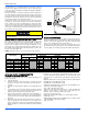
IGNITION SYSTEM SEQUENCE
1. Turn the gas supply ON at external valve and main gas valve.
2. Set the thermostat above room temperature to call for heat.
3. System start-up will occur as follows:
a. The induced draft blower motor will start and come up to
speed. Shortly after inducer start-up, the hot surface ignitor
will glow for about 17 seconds.
b. After this warm up, the ignition module will energize (open)
the main gas valve.
c. After flame is established, the supply air blower will start in
about 30 seconds.
IMPORTANT: Burner ignition may not be satisfactory on first startup
due to residual air in the gas line or until gas manifold pressure is
adjusted. The ignition control will make 3 attempts to light before lock-
ing out.
With furnace in operation, check all of the pipe joints, gas valve connec-
tions and manual valve connections for leakage using an approved gas
detector, a non-corrosive leak detection fluid, or other leak detection
methods. Take appropriate steps to stop any leak. If a leak persists,
replace the component.
The furnace and its equipment shutoff valve must be disconnected from
the gas supply piping system during any pressure testing of that system
at test pressures in excess of 1/2 PSI (3.45 kPa).
The furnace must be isolated from the gas supply piping system by
closing the equipment shutoff valve during any pressure testing of the
gas supply piping system.
CALCULATING THE FURNACE INPUT
(NATURAL GAS)
NOTE: Burner orifices are sized to provide proper input rate using natu-
ral gas with a heating value of 1030 BTU/Ft
3
. If the heating
value of your gas is significantly different, it may be necessary to
replace the orifices.
1. Turn off all other gas appliances connected to the gas meter.
2. At the gas meter, measure the time (with a stop watch) it takes to
use 2 cubic ft. (0.0566 m
3
.) of gas.
3. Calculate the furnace input by using one of the following equa-
tions.
FIRE OR EXPLOSION HAZARD
Failure to follow the safety warnings exactly could result in serious
injury, death or property damage.
Never test for gas leaks with an open flame. Use a commercially
available soap solution made specifically for the detection of leaks
to check all connections. A fire or explosion may result causing
property damage, personal injury or loss of life.
TABLE 14:
Field Installed Accessories - Non Electrical
PART NO. DESCRIPTION USED WITH
1FB0318
Combustible Floor Sub-Base
50, 7512
1FB0319 7516,10016
1FB0320 10020,125
1BR0312
Bottom Filter Rack
50,7512
1BR0316 7516,10016
1BR0320 10020,125,150
1NP0366 Conversion Kit-Natural Gas to LP Gas
All Models1NP0367 Conversion Kit- Natural Gas to LP Gas- High Altitude
2802-321P Vent Pipe Extension