
Installation manual

66832-UIM-D-1205
Unitary Products Group 11
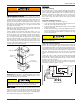
Filter(s) may be located in the duct system external to the furnace using
an external duct filter box attached to the furnace plenum or at the end
of the duct in a return filter grille(s). The use of straps and / or supports
is required to support the weight of the external filter box. Refer to Fig-
ures 10 and 12.
If the accessory electronic air cleaner is installed, be sure the air
cleaner is designed to accommodate the furnace CFM (cm/m) and the
air cleaner is installed so it does not obstruct the return airflow. Consid-
eration should be given when locating the air cleaner for maintenance
and temperatures should the indoor fan motor fail to operate. The use
of straps and / or supports is required to support the weight of the elec-
tronic air cleaner. It is recommended that the air cleaner not be located
within 12 inches (2.5 cm) from the top of the return air opening on the
furnace. Refer to the instructions supplied with the electronic air
cleaner.
If pleated media air filters or any filter that has a large pressure drop is
installed in the return air duct system be sure that the pressure drop
caused by the air filter will not prevent the furnace from operating within
the rise range specified on the rating plate. If the furnace does not oper-
ate within the specified rise range then a larger air filter or an air filter
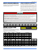
that has a lower pressure drop must be installed. Refer to Table 16 and
the furnace accessories for accessory external filter kit options.
IMPORTANT: For easier filter access in a downflow configuration, a
removable access panel is recommended in the vertical run of the
return air plenum immediately above the furnace.
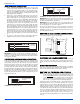
Accessory External Filter Installation
1. Install the return filter rack on the top of the furnace return air
opening. Secure the filter rack to the front and back flanges with
screws. The return air plenum can be placed over the filter rack
and the branch ducts (rectangular ducts and / or round ducts) can
be attached to the plenum. Route the combustion air and the vent
PVC pipes around the access panels for the filters.
2. Install the filter(s) provided or you may install Permanent washable
filters. Filter should extend through the entire length of the filter
rack to prevent air from bypassing the filter.
IMPORTANT: Air velocity through throwaway type filters must not
exceed 300 feet per minute (1.52 m/m). All velocities over this require
the use of high velocity filters. Refer to Table 16.
SECTION IV: GAS PIPING
GAS SAFETY
.
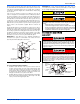
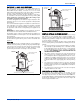
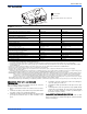
FIGURE 12: Return Filter Grill and Return Duct Installation
VENT
PIPE
GAS SUPPLY
(EITHER SIDE)
CLOSET
RETURN
AIR
AIR
FILTERS
All installations must have a filter installed.
For applications requiring more than 1800 CFM, it is required to use
the bottom return, both side returns or one side plus the bottom
return.
• Single side return is not approved on 5 Ton models.
• 18” minimum height for return air box for bottom return only on
Heating only applications with furnace in the upflow configuration.
• 24” minimum height for return air box for bottom return only on A/
C applications with furnace in the upflow configuration.
This furnace is designed to operate on NATURAL GAS or PRO-
PANE GAS ONLY. Do not burn any other fuel in this furnace. Burn-
ing any fuel except NATURAL GAS or PROPANE GAS can cause
premature heat exchanger burnout, high levels of carbon monox-
ide, excessive sooting, a fire hazard, personal injury, property dam-
age and /or death.
An overpressure protection device, such as a pressure regulator,
must be installed in the gas piping system upstream of the furnace
and must act to limit the downstream pressure to the gas valve so it
does not exceed 0.5 PSI (14" w.c. (3.48 kPa). Pressures exceeding
0.5 PSI (14” w.c. (3.48 kPa) at the gas valve will cause damage to
the gas valve, resulting in a fire or explosion or cause damage to
the furnace or some of its components that will result in property
damage and loss of life.
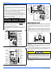
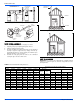
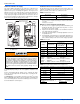
FIGURE 13: Gas Valve
INLET
WRENCH
BOSS
INLET
PRESSURE
PORT
ON
OFF
ON/OFF SWITCH
(Shown in ON position)
MAIN REGULATOR
ADJUSTMENT
OUTLET
OUTLET
PRESSURE
PORT
VENT PORT