
Installation manual


035-19599-001 Rev. A (1103)
Unitary Products Group 13
COMBUSTION AIR/VENT PIPE SIZING
Select the correct size from Table 9. The size will be determined by a
combination of furnace model, total length of run, and the number of
elbows required. The following rules must also be observed.
1. Long radius (sweep) elbows are required for all units.
2. Elbows are assumed to be 90 degrees. Two 45-degree elbows
count as one 90-degree elbow.
3. Elbow count refers to combustion air piping and vent piping sepa-
rately. For example, if the table allows for 5 elbows, this will allow a
maximum of 5 elbows in the combustion air piping and a maximum
of 5 elbows in the vent piping.
4. Three vent terminal elbows (two for vent pipe and one for air
intake pipe) are already accounted for as vent termination.
5. Combustion air and vent piping must be of the same diameter.
6. All combustion air/vent pipe and fittings must conform to American
National Standards Institute (ANSI) standards and American Soci-
ety for Testing and Materials (ASTM) standards D1785 (Schedule
40 PVC), D2665 (PVC-DWV), F891 (PVC-DWV Cellular Core).
D2241 (SDR-21 and SDR-26 PVC), D2261 (ABS-DWV), or F628
(Schedule 40 ABS. Pipe cement and primer must conform to
ASTM Standards D2564 (PVC) or D2235 (ABS).
7. The use of flexible connectors or no hub connectors in the vent
system is not allowed. This type connection is allowed in the com-
bustion air pipe near the furnace for air conditioning coil accessi-
bility.
8. Sidewall horizontal vent terminals and roof mounted vertical termi-
nals may be field fabricated. Standard PVC/SRD fittings may be
used. Terminal configuration must comply as detailed in this sec-
tion.
IMPORTANT: The minimum vent length is 5 ft. (1.524 m).
The maximum vent length is 60 ft. (18.29 m).
*. Vent pipe size must be increased to 3” diameter after connection to furnace on this model.
IMPORTANT: Accessory concentric vent / intake termination kits
1CT0302 and 1CT0303 are available and approved for use with these
furnaces.
IMPORTANT: Furnace vent pipe connections are sized for 2-in. pipe.
Any pipe size change must be made outside the furnace casing in a
vertical pipe section to allow proper drainage of condensate. An offset
using two 45º (degree) elbows will be required for plenum clearance
when the vent is increased to 3”.
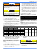
*. Elbow count does not include the elbows required for the termination. See Step 4 under Combustion Air/Vent Pipe Sizing.
NOTE: If installing furnace at altitudes between 2000 - 4500 ft., intake
and vent pipe length must be reduced by 10 ft. If the installation
requires the maximum allowable intake and vent pipe length,
the furnace must be converted for high altitude operation.
COMBUSTION AIR AND VENT PIPING ASSEMBLY
The final assembly procedure for the combustion air and vent piping is
as follows:
1. Cut piping to the proper length beginning at the furnace.
2. Deburr the piping inside and outside.
3. Chamfer (bevel) the outer edges of the piping.
4. Dry-fit the vent piping assembly from the furnace to the outside
termination checking for proper fit support and slope.
5. Dry-fit the combustion air piping assembly checking for proper fit,
support and slope on the following systems:
A. Sealed combustion air systems from the furnace to the out-
side termination.
B. Ventilated combustion air systems from the furnace to the
attic or crawl space termination.
6. Disassemble the combustion air and vent piping, apply cement
primer and the cement per the manufactures instructions. Primer
and cement must conform to ASTM D2564 for PVC, or ASTM
D2235 for ABS piping.
This furnace may not be common vented with any other appliance,
since it requires separate, properly sized air intake and vent lines.
The furnace shall not be connected to any type of B, BW or L vent
or vent connector, and not connected to any portion of a factory-
built or masonry chimney
The furnace shall not be connected to a chimney flue serving a sep-
arate appliance designed to burn solid fuel.
When combustion air pipe is installed above a suspended ceiling or
when it passes through a warm and humid space, the pipe must be
insulated with ½” Armaflex type insulation.
Vent piping must be insulated with 1/2” Armaflex insulation if it will
be subjected to freezing temperatures such as routing through
unheated areas or through an unused chimney.
TABLE 8:
Combustion Air Intake and Vent Connection Size at Furnace
(All Models)
FURNACE VENT CONNECTION SIZES
Furnace Input
40 - 100 MBH
(11.72-29.31 kW)
120 - 140 MBH
(35.17-41.03 kW)
Intake Pipe Size 2” (50.8 mm) 3" (76.2 mm)
Vent Pipe Size 2” (50.8 mm) 2"* (50.8 mm)
TABLE 9:
Combustion Air Supply and Vent Piping
MODELS Max. Elbows vs. One Way Vent Length (Ft.) (m)*
Heating
Input
Heating
Output
Heating
Input
Heating
Output
Furnace
Airflow
Furnace
Airflow
Pipe Size
Inches
Pipe Size
mm
5 - 30
(1.524 - 9.14)
35
(10.67)
40
(12.19)
60
(18.29)
BTU/H BTU/H kW kW CFM
m
3
/min
40,000 37,000 11.72 10.84 1000 28.32 2 50.8
654N/A
60,000 55,000 17.58 16.12 1200 33.98 2 50.8
80,000 75,000 23.45 21.98 1200 33.98 2 50.8
80,000 75,000 23.45 21.98 1600 45.31 2 50.8
100,000 95,000 29.31 27.84 2000 56.63 2 50.8
40,000 37,000 11.72 10.84 800 22.65 3 76.2
8 765
60,000 55,000 17.58 16.12 1200 33.98 3 76.2
80,000 75,000 23.45 21.98 1200 33.98 3 76.2
80,000 75,000 23.45 21.98 1600 45.31 3 76.2
100,000 95,000 29.31 27.84 2000 56.63 3 76.2
120,000 112,000 35.17 32.82 2000 56.63 3” only 76.2 mm only 6 5 4 N/A
Solvent cements are flammable and must be used in well-ventilated
areas only. Keep them away from heat, sparks and open flames.
Do not breathe vapors and avoid contact with skin and eyes.