
User's Manual

3.4DisplayConsole
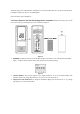
3.4.1 Display Console Layout
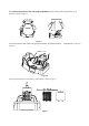
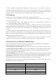
The display console layout is shown in Figure 11
Note: The following illustration shows the full segment LCD display for description purposes only and
will not appear like this during normal operation.
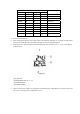
Figure 11
1. Outdoor temperature HI/LO alarm icon
2.Outdoor temperature display
3.Rainfall display(1h, 24h, week, month,
total)
4.Rainfall value for 24H
5.Press HI/LO alarm icon
6.Pressure ( ABS) display
7.Pressure (REL and ABS) display
8. WIFI network
9.Time
10. Time Alarm 1
11.Time Alarm 2
12
. Week or second
13.Time SYNC
14.Date
15.Indoor humidity display
16.Indoor humidity HI/LO alarm icon
17. 24hour for clear
18. Pressure units (Hpa,inhg and mmhg)
19. Rainfall units of measure
20.Outdoor humidity display
21.Scroll mode indicator
22. Channel 1,2,3,4,5,6,7,8 indicator
23.Wind direction
24. Wind gust HI alarm icon
25.Wind units (m/s,km/h)
26. Wind gust display
27.Wind speed average display
28.Wind average HI/LO alarm icon
29.Temperature units (°F or °C)