
User's Manual


6
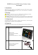
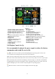
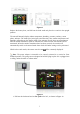
Figure 7
1
.In
d
oo
r
h
um
idi
ty c
h
ange
i
n
di
cat
i
on
2.Indoor humidity HI/LO alarm icon
3.Indoor temperature change indication
4.Temperature units (°F or °C)
5.Indoor temperature HI/LO alarm
icon
6.Outdoor humidity HI/LO alarm icon
7.Battery low voltage prompt
8.Moon phase
9.Reception icon
10.Outdoor temperature mode
11.Daylight Saving Time
12.Time
13.Weather tendency indicator
14.Time Alarm 1
15.Time Alarm 2
16
. T
i
me
S
YN
C
17. DATE
18. Wind direction
19. Wind speed units of measure
20.Wind speed Gust display
21.Wind speed average display
22.Wind speed average HI alarm icon
23. Rainfall display (1h, 24h, week, month,
total)
24.Pressure (REL and ABS) display
25. Rainfall units of measure
26.Pressure units of measure
27.WIFI network
28.24hour for clear
29.Indoorhumidity display
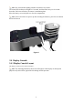
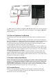
3.4.2Display Console Set Up
It is recommended to plug in the power supply to reduce the battery
consumption and extend the service life.
Note: The sensor array must be powered and updating before powering up the console, or the
console will time out searching for the sensors. Power the console last.
Make certain the weather station sensor array is at least 3m away from the console and within
30m of the console. If the weather station is too close or too far away, it may not receive a proper signal.
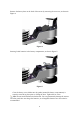
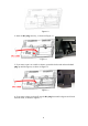
Remove the battery door on the back of the display, as shown in Figure 11. Insert three AAA (alkaline
or lithium)) batteries in the back of the display console. The display will beep once and all of the LCD
segments will light up for a few seconds to verify all segments are operating properly.
Note: The character contrast is best from a slightly elevated viewing angle.