
Specifications


18
INV2500-HS & INV5000-HS SERIES
OPERATING MANUAL
later. After the Output OK LED is on, turn on the B side AC output breaker.
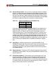
Check the AC voltage across the load with a digital AC voltmeter. The voltage
should be between 115 and 120VAC or between 230 and 240VAC, depend-
ing on the model.
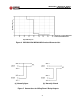
14.6 Check the Form C Relay contacts with an ohmmeter. See Figure 3. Measure
the resistance between the N.O. contacts and C contacts. They should
indicate an open. Measure the resistance between the N.C. contacts and the
C contacts. They should indicate a short.
14.7 Turn off the AC output circuit breakers first, followed by the DC input break-
ers, by placing the toggles in the down position. Test each inverter in the
manner described above.
15.0 INVERTER APPLICATION
15.1 In the actual application of the inverter, follow the procedure in sections 14.2
through 14.6, except the inverter should be connected to its actual load. The
loads connected to the output of the inverter should always have their own
individual circuit breakers. Make connections to the Form C relay contacts as
required. Then re-install the rear plastic safety cover.
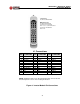
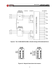
15.2 For two or more inverters in parallel, make the input and output connections
to the inverters as described in Section 13.0. See Figure 9. Put all output
distribution circuit breakers in the off position. Connect the sync terminals
together observing proper polarity.
15.3 Take one of the inverter modules and turn the DC input circuit breaker on;
then after the Output OK LED has come on, turn the AC output circuit
breaker on. This sequence must be performed for the inverter A side and
then the B side. Repeat this for each paralleled inverter in turn until all invert-
ers are on. Make sure that the three green LEDs are on for each inverter.
15.4 With all inverters on, turn on each AC output distribution circuit breaker. The
inverters will automatically share output currents to an accuracy of ± 10%.