
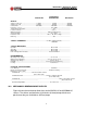
Specifications


16
INV2500-HS & INV5000-HS SERIES
OPERATING MANUAL
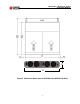
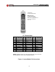
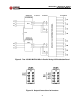
13.4 Figure 9 shows four INV2500-HS inverter modules in two INVR2U-HS
shelves connected in parallel to give 10KVA of AC output at 115VAC. The AC
output is distributed by a DPAC1UT AC Distribution Panel made by
UNIPOWER Telecom. Note that only 115VAC inverters can be used with the
DPAC1UT distribution panel and not the 230VAC INV5000-HS. 230VAC
INV5000-HSs require breakers on both line sides, and this is not available
with the DPAC1UT. Note also that only the “T” (Terminal Strip) Option of the
DPAC1U can be used with these inverters and that, as shown in Figure 9,
the A side AC input terminals must be strapped in parallel, i.e., A1G to A2G,
A1N to A2N and A1L to A2L; in the same way, the B side AC input terminals
must also be strapped in parallel.
14.0 INSTALLATION AND TESTING
14.1 The inverter or inverters should be initially tested in their shelves. For 23-inch
rack mounting use panel extenders.
14.2 Put all input and output circuit breakers in the off (down) position. See Figure
3. Remove the rear plastic safety cover.
14.3 Connect the input battery to the -48VDC and 48VDC Return input bus bars
by means of the 1/4-20 studs. Connect the input ground (10-32 stud) to the
system ground. Make sure the correct polarity is used and make sure the
connections are clean and firm. Reversed input polarity could cause damage
to the inverter.
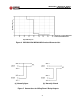
14.4 Connect the AC output cable to the proper output screw terminals. See
Figure 10 for the correct connection for 115 or 230VAC output versions.
Connect a load of approximately 10 amperes across the output of the inverter.
WARNING: When using “floating neutral” (Option E) in the INV2500-HS
module or INV5000-HS system, the AC neutral output terminal “N” is
floating with respect to chassis ground. A neutral-to-ground connec-
tion must be re-established external to the inverter and be in compli-
ance with the requirements of the end-use application.
14.5 To power up the inverter, turn the A side (left) DC input circuit breaker on by
moving the toggle to the up position. The A side fans and input OK and Sync
OK LEDs should come on followed by the Output OK LED approximately four
seconds later. After the Output OK LED is on, turn on the A side AC output
breaker by placing the toggle in the up position. Next, turn the B side (right)
DC input breaker on. The B side fans and Input OK and Sync OK LEDs
should come on followed by the Output OK LED approximately four seconds