
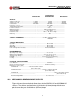
Specifications


11
INV2500-HS & INV5000-HS SERIES
OPERATING MANUAL
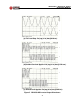
12.4 Overload Characteristic. These inverters incorporate electronic shutdown
circuitry; shutdown takes place during an overload, before the output circuit
breaker trips. Figure 5 shows INV2500-HS output voltage and current wave-
forms for a full load step, sudden overload, and short circuit. Figure 6 shows
shutdown time versus output current for both the INV2500-HS and INV5000-
HS. Below is a table that shows the same data in a different format:
Table 12-1. Typical Load Current vs. Shutdown Time
As the table shows, the INV2500-HS and INV5000-HS are capable of han-
dling large output surge currents, specifically more than three times rated
output current for 1/4 second, more than twice rated output current for 1
second and more than 1.5 times rated output current for 10 seconds. If the
surge exceeds approximately 318% of rated output current or exceeds the
shutdown times shown in the table, the output will be shut down and must be
reset by turning both input and output circuit breakers off. After this, the
input breaker(s) should be turned back on (up position); after the Output OK
LED(s) come on the output breaker(s) should be turned back on (up posi-
tion).
12.5 Grounding. It should be noted that in the standard INV2500-HS and
INV5000-HS models, both AC ground and AC neutral are connected to case/
shelf ground. For Option E versions, AC neutral is floating and must be
externally connected to system ground. In both versions the DC input termi-
nals are both floating.
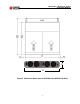
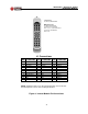
12.6 Status Indicators. Three green LEDs indicate the operating status of each
INV2500-HS inverter module. They are (from top to bottom): Input OK, Sync
OK and Output OK.
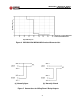
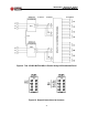
12.7 Form C Relay Contacts. These contacts have normally open (N.O.) and
normally closed (N.C.) positions for normal operation of each inverter. See
Figure 3 for connections. Note that there is a separate set of contacts for
each half (A and B sides) of the inverter. If it is desired to monitor the inverter
as a whole, the two sets of contacts may be connected as shown in Figure 7
to give an OR function for either set of contacts.
114-173% 10 sec.
173-223% 1 sec.
223-318% 0.25 sec.
PERCENT OF
RATED LOAD
SHUTDOWN
TIME