
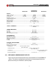
Specifications


10
INV2500-HS & INV5000-HS SERIES
OPERATING MANUAL
11.0 SAFETY AND INDUSTRY STANDARDS
11.1 The INV2500-HS and INV5000-HS inverters meet the following safety
certifications:
STANDARD AGENCY
UL1950 UL
CSA22.2 No.950 CUL
EN60950 DEMKO
11.2 The INV2500-HS and INV5000-HS inverters are CE marked to indicate
conformance to the European Union’s Low Voltage Directive.
11.3 Input conducted EMI meets FCC20780 part 15J Curve A and EN55022
Curve A.
11.4 Input voice band noise is less than 32dBrnC for a single INV2500-HS with a
240 ampere-hour battery or an INV5000-HS or two INV2500-HSs with a 480
ampere-hour battery.
12.0 OPERATING INFORMATION
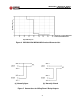
12.1 Input Voltage. These telecom inverters operate off a nominal 48VDC input
source which may be a battery or other DC source. The input voltage range is
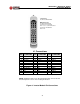
42 to 56VDC. Input connections on the back of the INV5000-HS and
INVR2U-HS are to bus bars with no. 1/4-20 studs.
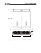
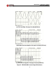
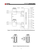
12.2 Output Voltage. The output voltage for an INV2500-HS is 115VAC at full
load, 120VAC at no load; for an INV5000-HS it is 230VAC at full load,
240VAC at no load. See Figure 5(a). Frequency is 50 or 60Hz, ±0.1%. The
output voltage has total harmonic distortion of less than 2.0%. The load
current crest factor is 2.8 to 1, and surge capability is up to 300%. The output
will drive reactive loads with up to ±90
o
phase angle. The output connectors
are screw terminals on the back of the INV5000-HS or INVR2U-HS.
12.3 Output Power. Maximum output power for an INV2500-HS is 115VAC at
22A RMS giving a maximum of 2530 volt-amperes. For an INV5000-HS it is
230VAC at 22A RMS, giving a maximum of 5060 volt-amperes. Exceeding
these values may cause electronic shutdown of the output. Full output power
is produced at up to 50
o
C ambient temperature. Above this, output current
must be derated at 2.5%/
o
C. Maximum operating temperature is 70
o
C, at
which the output current must be derated by 50%.