
User's Manual
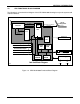


SECTION II INSTALLATION
SM 7063 07/97 2-4
2.3.3 Antenna and Cable Installation
Install the UHF antenna at least 6" from the edge of the locomotive roof and at least 12" from any other
fixture on the roof. Try to keep the cable run as short as possible.
If interference from a nearby transmitting antenna (e.g. voice radio) is likely to be a problem, locate the
antenna as far away as possible.
Affix the antenna cable in place and terminate it in a PL-259 UHF connector. Use only a high quality low
loss antenna cable such as RG-213/U.
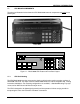
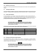
2.3.4 CDU Datalogger Connector
All CDUs are equipped with a DATALOGGER port connector. This is a 25-pin serial RS-232/C “D” type
connector mounted on the rear panel. Four of the 25 pins are used as listed in the table below:
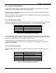
Pin DATALOGGER Connector
1 Chassis Ground (Shield)
2 Receive Data (RX DATA)
3 Transmit Data (TX DATA)
7 Signal Ground
Table 2-4. CDU DATALOGGER Port Connections
The connector is designed to operate as a DCE type serial port where pin 2 is used to receive data
from a remote serial device and pin 3 is used to transmit data to a remote serial device. This allows for
the use of a “straight-through” (not a null modem) type serial cable.
Note that Chassis Ground and Signal Ground are isolated from each other. The serial
communications parameters (baud rate, etc.) are configurable via a Diagnostic PC as described in
Section IV of this manual.
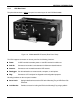
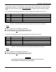
2.3.5 Event Recorder Connector
For CDUs equipped with a circular Event Recorder connector, the connector pin assignments are as
follows:
Pin Event Recorder Connector
A Receive Data (RX DATA)
B Transmit Data (TX DATA)
C Signal Common
D Chassis (SHIELD)
E Spare 1
F Spare 2
Table 2-5. CDU Event Recorder Connections