
User's Manual


SECTION I INTRODUCTION
SM 7063 07/97 1-9
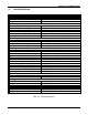
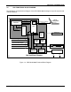
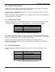
1.8 CDU FUNCTIONAL BLOCK DIAGRAM
The following is a functional block diagram of the CDU Model 6696 showing its major sub-systems and
external interfaces.
Cab Unit Block Diagram
Transceiver
CPU
Boot
EPROM
System
RAM
Parameter
EEPROM
Key XMTR
General Digital Inputs
Internal
UART
Lap-top
for Diagnostics
Transmit
Audio
MODEM
Receive
Audio
Front Panel Displays
Front Panel Switches
2
10
12
Sleep
Carrier Detect
Diagnostics and Calibration
Information
DUAL
CHANNEL
UART
2
Reverser Switch Inputs
Axle Alternator Input
1
4/3/96
1
20/60 PPR Axle Alter. Select
Power Supply
or
or
+12VDC +74VDC
Datalogger or
Event Recorder Device
FLASH
RAM
Figure 1-4. CDU Model 6696 Functional Block Diagram