UNION SWITCH & SIGNAL 645 Russell Street Batesburg, SC 29006 Service Manual 7063 R Digitair Model 6696 End-of-Train Communication Display Unit Installation Operation October 1996 July 1997 COPYRIGHT 1995, UNION SWITCH & SIGNAL Switch & Signal Inc.
TABLE OF CONTENTS SM 7063 07/97 ii
TABLE OF CONTENTS I INTRODUCTION............................................................................................................. 1-1 1.0 1.1 1.1.1 1.2 1.3 1.4 1.5 1.5.1 1.5.2 1.5.3 1.5.4 1.6 1.7 1.7.1 1.7.2 1.7.3 1.8 PURPOSE OF MANUAL................................................................................................. 1-1 GENERAL OVERVIEW................................................................................................... 1-1 CDU FUNCTIONAL DESCRIPTION .............
TABLE OF CONTENTS III OPERATION ................................................................................................................. 3-1 3.0 CDU OPERATING INSTRUCTIONS ............................................................................. 3-1 3.1 Purpose and Use of ID Code ......................................................................................... 3-1 3.2 Radio Communication Channel ......................................................................................
TABLE OF CONTENTS 3.13 EMERGENCY BRAKE APPLICATION ........................................................................ 3-27 3.14 COMMUNICATION TEST ............................................................................................ 3-28 3.15 AUTOMATIC COMMUNICATION TEST ..................................................................... 3-28 3.16 CDU DATALOGGER PORT ........................................................................................ 3-29 3.16.1 Data Logger Format .......
TABLE OF CONTENTS APPENDIX A SOFTWARE UPGRADES ..................................................................................A-1 A.1 A.2 A.3 A.4 CDU Software Upgrades ................................................................................................ A-1 Cab Unit Flash Loader Program ..................................................................................... A-1 Using “load.exe” ......................................................................................................
SECTION I INTRODUCTION 1.0 PURPOSE OF MANUAL This manual provides general information on the DIGITAIR End-of-Train Telemetry System and detailed information on the installation and operation of the Model 6696 Communication Display Unit (CDU). Refer to Service Manual SM 7064 for detailed Shop Maintenance information. 1.
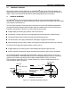
SECTION I INTRODUCTION 1.1.1 CDU FUNCTIONAL DESCRIPTION The CDU mounts in the locomotive cab; it connects to an antenna mounted on the roof and to the DC power system (72 VDC nominal). Separate connectors are provided for connection to the locomotive Axle Alternator (odometer), a Datalogging device, and a Diagnostic computer.
SECTION I INTRODUCTION 1.3 PATENTS AND TRADEMARKS Patents have been granted or are pending on items described in this manual. In the USA, the following patents have been applied for or have been granted: Railway Brake Pressure Monitor, Patent 4,487,060 Coupler Mount Assembly, Patent 4,520,662 Rechargeable Battery Pack, Patent 4,554,221 Similar patent applications have been made or are being made in Canada and Australia. DIGITAIR® is a registered trademark of Union Switch & Signal Inc. 1.4 R.A.I.L.
SECTION I INTRODUCTION 1.5.2 Parts Used for Installation Table 1-1 below lists parts used for installation which may be ordered separately from the CDU.
SECTION I INTRODUCTION 1.6 CDU SPECIFICATIONS Parameter Physical: Overall Dimensions Weight Environmental: Operating Temperature Range Storage Temperature Range Humidity Vibration - any axis, peak-to-peak Shock - (11 msec triangular, 3 planes) Altitude Power Requirements: 72 VDC Locomotive Power, Floating Current Consumption @ 72 VDC 13.6 VDC Power Input (Negative Ground) Current Consumption @ 13.
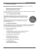
SECTION I INTRODUCTION 1.7 CDU MAJOR COMPONENTS The photo and illustration below shows the CDU Model 6696 external components and typical front panel layout. Union Switch & Signal Inc. ID = 85323 PRESSURE MARKER ON MOVING LOW BATTERY STOPPED R TO F FAILURE F TO R FAILURE ALARM COMM ARM MENU UP SET CANCEL MENU DOWN E M E R G E N C Y Figure 1-1. - Model 6696 CDU Features & Front Panel Layout 1.7.
SECTION I INTRODUCTION 1.7.2 CDU Rear Panel The photo below shows a typical rear panel connector layout for the CDU Model 6696. Figure 1-2. Model 6696 CDU Features (Rear Panel View) The CDU supports connectors on its rear panel for the following functions: Power: 72 VDC nominal locomotive power or 13.6 VDC nominal for mobile use. Axle Alt.: Connects to locomotive’s axle alternator for Odometer related functions. Antenna: Connects to roof mounted locomotive UHF antenna.
SECTION I INTRODUCTION 1.7.3 CDU Major Assemblies The photo below shows a top view of the CDU with its cover removed exposing the major assemblies. The unit has been designed using a modular approach for ease of production and user maintenance. Figure 1-3. Model 6696 CDU Features (Top Internal View) The CDU is comprised of the following three (3) major sub-assemblies: Front Panel Assembly: Contains the Processor Board, LED Display Driver Board, Display Panel, and Emergency Switch Assembly.
SECTION I INTRODUCTION 1.8 CDU FUNCTIONAL BLOCK DIAGRAM The following is a functional block diagram of the CDU Model 6696 showing its major sub-systems and external interfaces.
SECTION I INTRODUCTION SM 7063 07/97 1-10
SECTION II INSTALLATION 2.0 INSTALLATION OF THE CDU This section details the installation of a CDU into the locomotive cab environment. Two versions of CDU mounting arrangements are available: 1. CDU mounted on a Mounting Tray. 2. CDU mounted in an AAR Clean Cab Enclosure. 2.1 General Description The locomotive equipment comprises a Model 6696 Communication Display Unit (CDU). Available accessories include (refer to Table 1.
SECTION II INSTALLATION 2.2.2 AAR Clean Cab Enclosure Installation of an industry standard AAR Clean Cab Enclosure in the locomotive is the responsibility of the Railway. 2.3 Installing the CDU Cables This section details the installation of the Power and Odometer cables required to connect the CDU to the locomotive. The cables and their respective part numbers are listed in Table 1-1 in the previous section. 2.3.
SECTION II INSTALLATION Cut the odometer cable to the desired length. Strip and install whatever spade lug, tab, or other contact is required for the locomotive. The shield wire(s) connects to the CDU chassis at the connector end; cut the shield wire(s) at the locomotive end and leave unconnected. The cables should be wired per the tables below.
SECTION II INSTALLATION 2.3.3 Antenna and Cable Installation Install the UHF antenna at least 6" from the edge of the locomotive roof and at least 12" from any other fixture on the roof. Try to keep the cable run as short as possible. If interference from a nearby transmitting antenna (e.g. voice radio) is likely to be a problem, locate the antenna as far away as possible. Affix the antenna cable in place and terminate it in a PL-259 UHF connector.
SECTION II INSTALLATION 2.4 MOUNTING THE CDU This section details mounting the CDU onto the Mounting Tray or in the AAR Clean Cab Enclosure. 2.4.1 72 VDC / 12 VDC Power Selection Jumper (JP1) The CDU can be powered from either the standard 72 VDC locomotive power system or a 13.6 VDC (nominal) power source such as an automobile lighter socket. An internal Power Selection Jumper (JP1) located on the Base Assembly allows the user to select one power source or the other.
SECTION II INSTALLATION 2.5 BRIEF OPERATIONAL TEST OF THE CDU Upon receipt of a new CDU, it is recommended that the unit be briefly tested as described in this section to verify correct operation. This is performed in conjunction with a known operational End Unit. 2.5.1 CDU Power-Up Sequence Upon CDU power-up, verify that the following display sequence is indicated on the CDU’s Front Panel: The 32-Character LED Display (Function Menu Display) shows “Self Test in progress” accompanied by a beep tone.
SECTION II INSTALLATION 2.5.2 CDU Functional Check Perform the following basic steps to verify that the CDU is functioning correctly: Obtain a known operational End Unit. It may be operated within the locomotive without damage and no pressurized air is necessary. Power-up the CDU, observe it completes its power-on sequence, and then enter the ID code of the End Unit into the CDU.
SECTION II INSTALLATION SM 7063 07/97 2-8
SECTION III OPERATION 3.0 CDU OPERATING INSTRUCTIONS This section provides detailed information on the CDU’s various operating modes and functions, and how each one is used. 3.1 Purpose and Use of ID Code Each End Unit has a unique 5-digit numeric Identification Code (ID Code) assigned by the AAR “Central Train Information System Clearinghouse”. The ID Code is programmed into each End Unit and is a part of every message it transmits.
SECTION III OPERATION 3.3 DESCRIPTION of CDU FRONT PANEL DISPLAYS and CONTROLS All of the CDU Model 6696 operating displays and controls are located on the Front Panel and are arranged for easy use by the locomotive operator. Figure 3-1 below illustrates the CDU’s front panel layout. Brake Pressure Display Function Menu Display ID Code Display Armed Status LED (Optional) Union Switch & Signal Inc.
SECTION III OPERATION 3.4.2 Message Receipt Indicator in Pressure Display The right most decimal point in the Brake Pressure Display will blink ON briefly each time a valid message with the correct ID is received by the CDU. This indicator is provided as an aid to the operator in determining if messages are being received from the End Unit. 3.4.3 ID Code Display The primary purpose of this 8-character alpha-numeric display is to indicate the currently entered EOT ID code.
SECTION III OPERATION 3.4.4 Function Menu Display This 32-character alphanumeric display indicates the various menus items selected by pressing the MENU UP or MENU DOWN function keys. It is also used to display temporary information resulting from actions performed by the operator. All of the menu items except “View and Change End Unit ID Code” can be enabled or disabled via configuration using the Diagnostic PC to accommodate Railway specific needs (these are all detailed in Section IV).
SECTION III OPERATION 3.4.5 LED Annunciators A separate bank of seven (7) rectangular LED annunciators are provided to alert and draw the attention of the locomotive operator to important conditions. These are color coded Red or Green to indicate alarm or status conditions, respectively. In the case where additional information about a particular annunciator is required, a corresponding message is displayed on the ID Code Display. ID Code Display Union Switch & Signal Inc.
SECTION III OPERATION 3.4.6 ARMED Status LED (Optional) Three versions of the CDU front panel are available; (1) panel marked with ARMED, (2) panel marked with NOT ARMED, and (3) no marking (Armed Status LED not used). Depending on the version of front panel equipped on the CDU, this Green LED can be configured via the Diagnostic PC (see Section IV) to be turned ON or OFF as follows: 1.
SECTION III OPERATION 3.5 FUNCTION KEYS The CDU Function Keys consist of nine (9) pushbuttons. These are illuminated ("back-lit") for readability at night. All CDU functions are performed using these keys. Union Switch & Signal Inc.
SECTION III OPERATION 3.6 EMERGENCY BRAKE SWITCH The Emergency Brake Switch is only operational if the CDU is operating in Two-Way mode and is “Armed” to the End Unit ID code being displayed in the ID Code Display. When the operator flips this switch, the CDU transmits the emergency braking command to the End Unit. To help prevent unintentional activation, this switch is protected with a spring loaded RED switch guard forcing the user to consciously select it.
SECTION III OPERATION 3.8 OPERATION of CDU FUNCTION MENU ITEMS This section provides a detailed description on the use each of the CDU’s Function Menu Items. Use the MENU UP or MENU DOWN key to select the desired Function Menu Item, as required. 3.8.1 Viewing and Changing the ID Code Many trains can exist in close proximity to one another, therefore each CDU/End Unit pair must have a way to identify messages that are coming from its "mated" unit. Sharing a unique ID code is how this is done.
SECTION III OPERATION If the CDU is configured to operate with the “Arming” security feature, the ALARM annunciator will flash ON accompanied by 5 beeps from the sonalert, and the ID Code Display will show: " ID = ##### " alternating with “ NOT ARMD” if the CDU has not yet been Armed to the new ID Code (See Section 3.10 - “Arming” process). If the SET key is pressed during the 5 second window, the CDU will switch to One-Way operation and the Function Menu Display will indicate: " Changing mode ...
SECTION III OPERATION 2. If the ID code digits have been changed but the SET key has not yet been pressed to store the new ID code, pressing the CANCEL key will cause the ID code to revert back to its original value. 3. Refer to Section 3.10 for a full description of the Arming process. 3.8.1.
SECTION III OPERATION 3.8.3 Measuring Distance Traveled Using the Odometer (Count Up from Zero) 1. To use the Odometer, press the MENU UP or MENU DOWN key until the Function Menu Display reads: “Odometer: press SET “ 2. To measure distance, press the SET key.
SECTION III OPERATION 3.8.4 Using the Train Length Distance Function (Count Down to Zero) Since a train can approach 2 miles in length, it is not always practical for the locomotive operator to single-handedly determine if the rear end of the train has cleared a siding entrance or track junction so that it will not interfere with the passage of another train or highway traffic.
SECTION III OPERATION 3.8.5 Calibrating the Odometer Using a Measured Mile Calibration of the Odometer is used to compensate for locomotive wheel wear and differences in wheel diameter from one locomotive to another. The allowable range of locomotive wheel diameters is 34.00 inches through 46.00 inches. The CDU’s default value is 40.00 inches. Calibration of the wheel diameter can be done in one of two ways: Direct Entry though the use of the Diagnostic PC (see Section IV).
SECTION III OPERATION 3.8.6 Viewing the Locomotive Wheel Size To view the currently stored wheel size (diameter), press the MENU UP or MENU DOWN key until the Function Menu Display reads: " Wheel Size = ##.## inches " where ##.## is the calculated locomotive wheel diameter based on the measured mile calculation or the value entered using the Diagnostic PC. The allowable wheel diameter range is 34.00 inches through 46.00 inches. The CDU is shipped with a default value of 40.00 inches.
SECTION III OPERATION 3.8.8 Viewing Train Acceleration To view train acceleration, press the MENU UP or MENU DOWN key until the Function Menu Display reads: “ Acceleration = ### mph/min “ where ### is the acceleration value in miles per hour per minute. Negative values indicate deceleration. If the CDU is configured for Metric Units, the Train Acceleration is displayed in kilometers per hour per minute (kph/min).
SECTION III OPERATION 3.8.10 Display Secondary Air Pressure This function is made available for railways using dual pressure type End Units. It provides a secondary display of the air pressure for the auxiliary pressure source. To display the Secondary Air Pressure, press the MENU UP or MENU DOWN key until the Function Menu Display reads: “ Secondary Pressure: ### “ where ### is the 3-digit numeric value of the air pressure.
SECTION III OPERATION 3.8.11 Disarming the CDU When a CDU/End Unit pair are “broken up” (i.e., when the End Unit is moved from one train to another), it is desirable to "Disarm" the CDU so that it no longer has Emergency Brake control of the End Unit that is on the other train. This can be done in the following two ways: Method 1: Arming to “00000” 1. This method requires the operator to enter an ID code of "00000" in the same manner as described Section 3.8.1.
SECTION III OPERATION 3.8.12 Scanning for Incoming ID Codes The CDU has the capability to display the ID code portion of all uncorrupted messages it receives. 1. To view incoming End Unit ID codes, press the MENU UP or MENU DOWN key until the Function Menu Display reads: “ ID Scan: ##### ##### ##### “ where ##### are incoming End Unit ID codes. 2. Each End Unit ID code is displayed for a minimum of 5 seconds.
SECTION III OPERATION 3.8.15 Performing a CDU Self Test This function allows the locomotive operator to repeat the CDU power-on self test without having to power the unit OFF and back ON. 1. To select the Self Test function, press the MENU UP or MENU DOWN key until the Function Menu Display reads: “Self Test: press SET “ 2. The Function Menu Display will show the following test sequence: “Self Test in progress” “Union Switch & Signal Inc.
SECTION III OPERATION 3.10 ARMING the CDU to an END UNIT If the CDU is operating in the two-way mode and is configured to use the “Arming” security feature, it is necessary to first "authorize" the CDU to "talk to" the End Unit. This helps prevent undesired external devices or people from intentionally or unintentionally activating the emergency braking function. This process is called "Arming".
SECTION III OPERATION 3.10.1 Description of Arming Process 1. The operator at the end of the train relays the End Unit ID code to the locomotive operator via voice radio. 2. The locomotive operator enters the ID code of the End Unit into the CDU (see Viewing and Changing the ID Code, Section 3.8.1).
SECTION III OPERATION 3.10.2 Automatic Arming Not all railroads elect to use the relative security provided by the Arming technique. They may choose to use "Automatic Arming" instead. In this case, the CDU is always Armed to the entered ID code, the Emergency Switch is always enabled, and there is no need for an operator at the rear of the train. This feature is configurable via the Diagnostic PC (see Section IV).
SECTION III OPERATION 3.12 ALARM INDICATIONS The CDU incorporates 4 dedicated RED annunciators in conjunction with messages displayed on the ID Code Display to present alarm conditions to the locomotive operator. These operate as described in the following paragraphs. 3.12.1 Low Battery The LOW BATTERY annunciator turns ON to indicate the existence of a low battery capacity condition in the End Unit.
SECTION III OPERATION 3.12.2 Rear-to-Front Communications Failure (R TO F FAILURE) If no messages are received from the End Unit for a period of approximately 5 minutes 41 seconds, the CDU will flash the R TO F FAILURE annunciator 5 times accompanied by beeps from the sonalert and then remain ON. The Brake Pressure Display will indicate 3 dashes “ - - - “ since the pressure reading is now unknown. The R TO F FAILURE annunciator will remain lit until a valid message is received from the matching End Unit.
SECTION III OPERATION 3.12.4 ALARM Annunciator The ALARM annunciator operates in conjunction with the ID Code Display. When a system alarm condition is initially sensed by the CDU, it will cause the ALARM annunciator to flash 5 times together with a message on the ID Code Display indicating the nature of the alarm. This is accompanied by beeps from the sonalert.
SECTION III OPERATION 3.13 EMERGENCY BRAKE APPLICATION To apply the emergency brakes at the rear of the train, lift up the red switch guard and momentarily push the Emergency Switch upwards. The switch is spring loaded and will return to the down position when released. The CDU will immediately transmit an emergency brake command and its Function Menu Display will briefly show “EMERGENCY BRAKE INITIATED”.
SECTION III OPERATION 3.14 COMMUNICATION TEST If radio communications problems are suspected, the front-to-rear and rear-to-front radio links may be tested by momentarily pressing the COMM ARM key. When the COMM ARM key is pressed, the Function Menu Display shows: " WAITING FOR REPLY " for 2 seconds. Depending on the status of the reply, one of the following will be displayed: 1.
SECTION III OPERATION 3.16 CDU DATALOGGER PORT The CDU supports two Data Logger Port protocol output formats. These are configurable via the Diagnostic PC by selecting either “Data Logger Protocol” or “Event Recorder Protocol” (see Section IV). 3.16.1 Data Logger Format This section describes the data format output by the CDU in the case where it has been configured for “Data Logger Protocol” from the Diagnostic PC.
SECTION III OPERATION The character in position 4 is used to indicate the following: < + ! I U = = = = = Reply from End Unit is pending. Reply from End Unit is pending. Emergency Brake Application has been transmitted. The End Unit is operating in One-way mode. The CDU is in two-way mode but has not been armed. The character in position 5 is used to indicate status of the End Unit brake valve drive circuitry as follows: V = Brake Valve Drive Circuit Failure.
SECTION III OPERATION Defined ASCII Messages: In addition to the above characters, specific ASCII messages are transmitted by the Data Logger Port as follows: 1. If the CDU has a valid ID number but has not been armed to this ID, the message “ NOT ARMD “ is output to the Datalogger Port. Until such time as the CDU is armed to the End Unit with this ID, all subsequent outputs will carry the “U” in character position 4. 2.
SECTION III OPERATION 3.16.2 Event Recorder Format CDUs configured for “Event Recorder Protocol” conform to the data transfer protocol described in this section. 3.16.2.1 Electrical Characteristics Data is transmitted as follows: 1) RS-232/C Signal Levels 2) Asynchronous, serial 3) Baud Rate, Start Bit, Data Bits, Stop Bit, and Parity as configured via the Diagnostic PC. Standard event recorders typically require these to be set to 1200 Baud, 1 Start Bit, 8 Data Bits, 1 Stop Bit, and No Parity.
SECTION III OPERATION Note 1: Bit State Description 7 N/A Always set to 0. a EOT Dump Valve Status (ie., End Unit confirmation bit status) 0 1 b Inactive - Confirmation bit not set. Active - Confirmation bit set. EOT Type 0 1 c One-Way Rear EOT Unit. Two-Way Rear EOT Unit. HVM Light Status 0 1 d HVM Light OFF (ie., not flashing). HVM Light ON (ie., flashing). EOT Telemetry Battery Status 0 1 e Battery OK. Battery status is WEAK or REPLACE. EOT Message Status 0 1 f Regular 0.
SECTION III OPERATION Note 2: Bit State Description 7 N/A Always set to 0. t N/A Always set to 1. u N/A Always set to 1. v N/A Always set to 1. w N/A Always set to 1. x N/A Always set to 1. y HOT Emergency (CDU Emergency Switch Status) 0 1 z CDU Emergency Switch open (released). CDU Emergency Switch closed (active). HOT Type (One or Two Way Front Unit, Always 1 for CDU) 0 1 One-Way type Front EOT Unit. Two-Way type Front EOT Unit. Note 3: EOT Pressure information.
SECTION IV CONFIGURATION & DIAGNOSTICS 4.0 CONFIGURATION and DIAGNOSTICS A dedicated serial port, labeled DIAG, is located on the CDU’s Rear Panel Assembly. The port uses a standard 9-pin plug type RS-232/C “D” connector and interfaces to an IBM compatible PC via a “straight-through” off-the-shelf 9-pin serial cable. All CDU configuration and diagnostics are performed using the DIAG port in conjunction with Diagnostic Software running on a PC. 4.
SECTION IV CONFIGURATION & DIAGNOSTICS 7. To initiate the diagnostic Main Menu, press any of the CDU’s Function Control Keys. 4.2 Main Menu When the CDU is operating in diagnostic mode, the first screen displayed on the PC is the Main Menu. To select one of the submenus associated with Diagnostic Items or Configuration Items, type the desired menu item number and press .
SECTION IV CONFIGURATION & DIAGNOSTICS 4.3 Diagnostic Items This Diagnostic Items Menu displays selections which may show information about, or perform a diagnostic test on specific elements of the CDU. Select a diagnostic test from this menu by typing in a menu item number followed by . To return to the Main Menu, press . The use of the Diagnostic Items is beyond the scope of this manual. These are each described in detail in the CDU Shop Maintenance Manual, SM 7064. 4.
SECTION IV CONFIGURATION & DIAGNOSTICS 4.4.1 Set ID Code To read the currently stored ID code or modify the ID code without using the CDU Function Control Keys, select item “1” (Set Id Code) from the Main Configuration Menu and press . The following screen showing the current ID will appear: To modify the ID code, type in a new 5 digit ID code and press . The new ID code will be updated on the PC screen and will also be displayed on the CDU’s ID Code Display.
SECTION IV CONFIGURATION & DIAGNOSTICS 4.4.2 Set One-Way Protocol Type To read the current One-Way protocol setting or modify the protocol, select item “2” (Set One-Way Protocol Type) from the Main Configuration Menu and press . The following screen showing the current protocol will appear: To modify the protocol, type in the number of the desired protocol and press .
SECTION IV CONFIGURATION & DIAGNOSTICS 4.4.3 Set Two-Way Protocol Type To read the current Two-Way protocol setting or modify the protocol, select item “3” (Set Two-Way Protocol Type) from the Main Configuration Menu and press . The following screen showing the current protocol will appear: To modify the protocol, type in the number of the desired protocol and press .
SECTION IV CONFIGURATION & DIAGNOSTICS 4.4.4 Enable Two-Way Mode To read the current Mode setting or enable/disable the two-way mode, select item “4” (Enable TwoWay Mode) from the Main Configuration Menu and press . The following screen showing the current mode will appear: To default the initial power-up mode to One-Way or Two-Way Mode, type in the number of the desired mode and press . The selected mode will be the one used by the CDU when it is powered ON.
SECTION IV CONFIGURATION & DIAGNOSTICS 4.4.5 Set Low Pressure Threshold To read the current Low Pressure Threshold value or change the value, select item “5” (Set Low Pressure Threshold) from the Main Configuration Menu and press . The following screen showing the current value will appear: The factory default setting is 45 psig. When the brake pipe pressure drops below this value, the CDU will indicate a Low Pressure ALARM as a warning to the locomotive operator.
SECTION IV CONFIGURATION & DIAGNOSTICS 4.4.6 Configure Odometer To configure the odometer related functions for the type of units displayed (English or Metric) or to set the locomotive wheel diameter, select item “6” (Configure Odometer) and press . The following screen showing the associated submenus will appear: To select an item from this submenu, type in a menu item number and press . To return to the Main Menu, press . 4.4.6.
SECTION IV CONFIGURATION & DIAGNOSTICS 4.4.6.2 Set Wheel Diameter Submenu The screen below shows the current value of the locomotive wheel diameter: The factory default for the locomotive wheel diameter is 40.00 inches. To change the wheel diameter value, type in the numeric value of the wheel diameter in the range of 34.00 inches to 46.00 inches and press . To return to the Configure Odometer Menu, press .
SECTION IV CONFIGURATION & DIAGNOSTICS 4.4.7 Configure Data Logger To configure the Data Logger protocol and its associated transmission parameters, select item “7” (Configure Data Logger) and press . The following screen showing the associated submenus will appear: To select an item from this submenu, type in a menu item number and press . To return to the Main Menu, press . 4.4.7.1 Set Protocol The screen below shows the current data logger protocol selection.
SECTION IV CONFIGURATION & DIAGNOSTICS 4.4.7.2 Set Baud Rate The screen below shows the current baud rate setting. To change the baud rate setting, type in the desired submenu item number and press . To return to the Set Protocol menu, press . 4.4.7.3 Set Bits per Character The screen below shows the current bits per character setting. To change the number of bits per character, type in the desired submenu item number and press . To return to the Set Protocol menu, press .
SECTION IV CONFIGURATION & DIAGNOSTICS 4.4.7.4 Set Parity The screen below shows the current parity setting. To change the parity, type in the desired submenu item number and press . To return to the Set Protocol menu, press . 4.4.7.5 Set Number of Stop Bits The screen below shows the current setting of the number of stop bits. To change the stop bits setting, type in the desired submenu item number and press . To return to the Set Protocol menu, press .
SECTION IV CONFIGURATION & DIAGNOSTICS 4.4.8 Configure Armed Status LED Three versions of the CDU Front Panel are available to accommodate the Armed Status LED as follows: 1. Panel marked with NOT ARMED. LED turns ON when CDU is disarmed. 2. Panel marked with ARMED. LED turns ON when the CDU is armed. 3. Panel with NO marking. LED is not used. To configure the operation of the Armed Status LED, select item “8” (Configure Armed Status LED) and press .
SECTION IV CONFIGURATION & DIAGNOSTICS 4.4.9 Configure Customer String During the power-up sequence, the CDU displays the currently stored Customer String. To view or modify the customer string, select item “9” (Configure Customer String) and press . The following screen showing the customer string will appear: To modify the Customer String, type in the desired alphanumeric string (e.g., “XYZ Railway Inc.”) and press . To return to the Main Configuration Menu, press .
SECTION IV CONFIGURATION & DIAGNOSTICS 4.4.10 Configure Front Panel Menu As listed in Table 3.1, each CDU menu function can be enabled or disabled depending on specific Railway requirements. When a Function Menu Item is disabled, it will NOT appear in the Function Menu Display when the MENU UP or MENU DOWN key is pressed. To view the Front Panel Menu items, select item “10” (Configure Front Panel Menu) and press .
SECTION IV CONFIGURATION & DIAGNOSTICS 4.4.11 Enable Automatic Arming For railroads who choose NOT to use the ARMING security feature, Automatic Arming can be enabled via this menu item. Enabling Automatic Arming, in effect, puts the CDU into an always armed mode. In this case, no operator is required at the rear of the train and the activation of the Emergency Switch will cause the transmission of an emergency brake command containing the currently entered ID Code.
SECTION IV CONFIGURATION & DIAGNOSTICS 4.4.12 Set Transmit Power Level The CDU normally transmits Emergency brake commands to the End Unit at 2 Watts RF power. The CDU has the capability to transmit at higher power levels as required by the Railroad. To select the transmit power level, type in “12” (Set Transmit Power Level) and press . The following screen shows the currently selected setting: The factory default setting is typically “0” for the 2 Watt power level.
SECTION IV CONFIGURATION & DIAGNOSTICS 4.4.13 Allow Changing Between One and Two Way Operation The CDU has the capability to operate in either one-way or two-way mode. If this configuration item is set to ON, the CDU will prompt the user to select the operational mode immediately after a new ID Code has been entered. If the value is set to OFF, the CDU will not prompt the user and will simply save the new ID Code and operate in two-way mode at all times.
SECTION IV CONFIGURATION & DIAGNOSTICS 4.4.14 Blanking the Function Menu Display During No Activity This configuration item is only applicable when the CDU’s Change ID Menu Item is being viewed. If this configuration item is enabled, and none of the CDU’s Function Keys are pressed for a period of 2 minutes, the CDU will display the currently entered Customer String (e.g., ABC Railroad) for 2 minutes and will then blank the Function Menu Display.
APPENDIX A SOFTWARE UPGRADES A.1 CDU Software Upgrades The CDU uses a FLASH type programmable non-volatile memory chip to store its application software as opposed to a standard EPROM. This eliminates the need to disassemble the unit and physically replace the EPROM in the event that software upgrades are issued. Software upgrades are supplied by US&S on a CDU Executable Software Disk containing two files; (1) the latest upgrade version of the CDU executable software named “cdu.
APPENDIX A SOFTWARE UPGRADES A.4 Procedure for Downloading CDU Software Upgrades To download CDU software upgrades, perform the following: 1. On the PC, copy the new Upgrade Version of the file “cdu.hex” to the floppy disk or hard drive directory containing the Cab Unit Flash Loader Software “load.exe”. 2. Turn OFF power to the CDU. 3. Connect one end of the serial cable to the CDU’s DIAG connector and the other end to one of the PC’s serial ports (either COM1 or COM2).
APPENDIX A SOFTWARE UPGRADES SM 7063 07/97 A-1