
Instruction manual


Head, Probe and Sample Preparation
MultiMode SPM Voltage Meters
86 MultiMode SPM Instruction Manual Rev. B
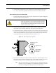
The bottom digital meter 2 reads differences in voltage between various segments of the
photodetector. With the mode switch toggled to AFM & LFM, it indicates the voltage difference
(C - D), that is, the left segments minus the right segments. With the mode switch toggled to TM
AFM (TappingMode), it indicates the voltage difference (A - B)—that is, the bottom segments
minus the top segments.
The topmost digital meter 3 indicates the output signal of the SPM. Depending upon the mode
selected, the topmost meter reads either the (A - B) voltage difference (mode switch toggled to
AFM & LFM), or the RMS voltage (mode switch toggled to TM AFM).
TappingMode
or Contact AFM
Output
Signal (V)
Vertical
or Horizontal
Difference Sum
RMS VERT
SUM
-2.6
0.00
8.4