
Instruction manual


Head, Probe and Sample Preparation
MultiMode SPM Voltage Meters
Rev. B MultiMode SPM Instruction Manual 85
3. Select the scanner you plan to use (Edit > Scanner).
Note: In the Microscope Select dialog box, you can add a new set of hardware
configuration parameters by clicking New or edit the parameters of the selected
microscope by clicking Edit. The parameters include things such as the
controller, extender, and vision system.
4. Select OK when you finish changing all microscope parameters.
5. In the Other Controls panel, select the Microscope Mode.
• For TappingMode, set the Microscope Mode to Tapping.
• For Contact AFM, set the Microscope Mode to Contact.
6. After this is completed, click on the Scan Controls panel to access the most important
control settings used for imaging.
5.4 MultiMode SPM Voltage Meters
• A complete description of the signals coming into and out of the MultiMode SPM is
available in Support Note 210, NanoScope Signal Access Module (SAM)—Description
and Use. The SAM is normally used for accessing these signals directly. A brief
description of the SPM’s voltages and their interpretation using the meters on the front
of the base is provided here for quick reference.
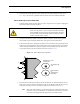
• The MultiMode SPM base is equipped with meters which indicate voltage coming from
the four-segment photodetector. The photodetector array is represented here:
• The MultiMode SPM’s bottom, (SUM) meter indicates the total voltage generated by
the photodetector. That is, the combined voltage of photodetector segments. This is
displayed during all modes (except STM when all meters are off).
Vertical deflection
Vertical deflection
Lateral deflection
Lateral deflection
B
A
CD