Manual PZ-series Portable Radio PZ-400, PZ-100
Maintenance Manual TABLE OF CONTENTS SPECIFICATIONS ................................................................................................................................................. 4 MODEL: PZ-100 ............................................................................................................................................. 4 MODEL: PZ-400 ...........................................................................................................................................
Maintenance Manual SCAN Operating mode.................................................................................................................................. 18 Emergency Call ............................................................................................................................................. 20 VOX .............................................................................................................................................................. 20 Monitor .....
Maintenance Manual SPECIFICATIONS MODEL: PZ-100 GENERAL Dimensions(Less Antenna) H x W x D Weight Radio (less battery) with battery (2600mAH) Programmable Channels Channel Spacing Power Source Current Drain (maximum) Receive Standby mode Receive Full Audio Transmit at 5 Watts 112.2 × 56mm × 31.9 mm 16 Channels 12.5 / 25 kHz 7.5V DC Rechargeable Li-ion 2600 mAH battery pack 60 mA 350 mA 1.
Maintenance Manual MODEL: PZ-400 GENERAL Dimensions(Less Antenna) H x W x D Weight Radio (less battery) with battery (2600mAH) Programmable Channels Channel Spacing Power Source Current Drain (maximum) Receive Standby mode Receive Full Audio Transmit at 5 Watts 112.2 × 56mm × 31.9 mm 512 Channels 12.5 / 25 kHz 7.5V DC Rechargeable Li-ion 2600 mAH battery pack 60 mA 350 mA 1.
Maintenance Manual MODEL NUMBER To identify the model number of PZ-series Radio is as followings PZ – 100 Identification number of radio Frequency Band manufactured by UNIMO Model Number Description PZ - 100 PZ - 400 Frequency band: 136 – 174 Mhz, Frequency band: 400 – 470 Mhz, PZ-SERIES RADIO PACKAGE NUMBERS Package Number Description PZ10XXXE PZ10GXXE PZ10XBXE PZ10GBXE 136 – 174Mhz PZ series radio 136 – 174Mhz PZ series radio with GPS 136 – 174Mhz PZ series radio with Bluetooth 136 – 174Mhz
Maintenance Manual FEATURES PZ-series radio is designed for a rugged, lightweight and it can be provided for powerful sound and for better performance of conversation distance & sound quality. The new PZ-series radio provides reliable service in the industrial fields and public places for the safety & convenience of users. The PZ-series radio is offered with several packages available with respect to the options (GPS function, Bluetooth function).
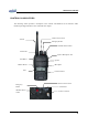
Maintenance Manual CONTROLS & INDICATORS The following section provides a description of the controls and Indicators for the PZ-series radio. Detailed operating instructions can be found the later chapter.
Maintenance Manual Controls On/Off Volume Switch Turn the knob of Volume Switch clockwise to turn the Radio on and if turning the Switch to the opposite direction, the Radio is turned off. The audio volume level can be adjusted by turning the Volume Switch and when adjusting the volume, please refer to the index mark indicated nearby the Volume knob. The knob of volume doesn’t exist for the GPS model of PZ-series radio. In this case, press and hold the “F4” button then the radio is turn ON.
Maintenance Manual emergency channel. Menu Button (Scan Button) If pressing Menu button for about 2 seconds, the Scan operation is proceeded and by pressing the Menu button again, the Scan operation is released.
Maintenance Manual ⑦ ④ ③ ② ① ⑤ ⑥ ⑧ ⑨ ⑩ ① Signal strength indicator is ON when the radio receives RF signal. It can be divided for 4 kinds of signal levels. In case of good signal, all 4 the signal strength indicator bar is ON. ② Transmitting power indicator is ON when the Low power mode is selected. ③ 2Tone, 5Tone mode indicator is ON when the channel is programmed for 2Tone, 5Tone operation. ④ VOX indicator is ON when the VOX mode is activated.
Maintenance Manual BATTERY PACKS The following battery pack is available for use with the PZ-series radio. PBX-2260LA: Rechargeable Battery Packs (2600mAH Li-ion). The PX-Series Radio receives power from high-performance Li-ion battery. The battery is safe, of high-performance and highly reliable. Using the enclosed standard charger makes it possible to get sufficient efficiency and lifetime of the battery. ☞ Battery Packs used with the PZ-series radio must be supplied by UNIMO Technology Co., Ltd.
Maintenance Manual Installing the Battery Pack Ensure the ON/OFF volume switch is set to OFF position of the radio. Hold the radio and battery pack with the back of them facing you. See Figure Align the hook back of the radio with the hook front side of the battery pack Press and slide the battery pack fully upper side of the radio until the battery release latch click into place.
Maintenance Manual Removing the Battery Pack Ensure the ON/OFF volume switch is set to OFF position of the radio. Press down the release latch and slide the battery pack down side of the radio.
Maintenance Manual Charging the Battery Pack New batteries or batteries that have been stored for a long time period of time, should be fully charged before placing into service. Low battery voltage will shorten the talk range and will make the performance of radio worse. When the battery pack requires charging the battery indicator in the LCD will blink and the radio will sound a high pitch tone every seconds. How to Charging Plug the charger (CHZ-260FB) into the electricity power outlet for AC220V.
Maintenance Manual When charging the battery only, insert battery into rear slot of the charger. Although the green LED is on after full charge, please continue the charging for 30 more minutes for the complete full charge. During the charging After complete charging Error condition During maintaining charge ☞ CAUTION red LED is turn ON green LED is turn ON red LED is blinks green LED is turn ON Charger used with battery packs must be supplied by UNIMO Technology Co., Ltd.
Maintenance Manual RADIO OPERATIONS Installation and Removal of Antenna Put the antenna into the antenna connector of the radio and turn the antenna clockwise for installation of antenna and in order to remove the antenna from Radio, turn the antenna counterclockwise. ☞ CAUTION` When installation of the antenna, giving a strong pressure to the Radio or pulling the antenna from Radio with a strong power can make damage on the antenna connector, which may cause the Radio to have critical problem.
Maintenance Manual Receiving The radio operates as a receiving standby mode except for the transmitting period. User can adjust the volume by using the volume switch. The green LED is turn ON when the radio receives the RF signal and can heard the transmitting voice. According to the setting of transmitting radio, can be heard the DTMF tone or 5 Tone and displayed caller ID on the LCD. If frequency is same as current channel but sub-tone is not same as current setting than the green LED blinks.
Maintenance Manual A scan channel list must be created before SCAN can be used. The radio will not go into SCAN mode where no scan channels are programmed. The scan channel list can be established in PC program of Menu mode. Normal Scan Once SCAN is activated, the radio will perform a normal scan mode. When the scan channel list is NS1, NS2 and NS3 on the normal scan mode, the radio proceeds to scan in the sequence of NS1, NS2, NS3, NS1, NS2, NS3....
Maintenance Manual Emergency Call If pressing the EMR key, radio transmitting the emergency alert tone or 5-Tone message in Sell-call mode. Also user can hear the emergency alert tone. If the radio is set up in repeated mode, the radio transmitting the emergency alert tone periodically. This function can be performed when SCAN is activated. VOX The VOX function is set up by Pc-Programmer and without pressing the PTT key, the voice signal is transmitted through microphone.
Maintenance Manual Subtone The radio can be programmed for CTCSS encode/decode tone frequencies and DCS code. CTCSS tone frequency A list of standard tone frequencies for CTCSS tone are as shown below. No. Frequency No. 1 2 3 4 5 6 7 8 9 10 11 12 13 14 67.0 71.9 74.4 77.0 79.7 82.5 85.4 88.5 91.5 94.8 97.4 100.0 103.5 107.2 15 16 17 18 19 20 21 22 23 24 25 26 27 28 Frequency 110.9 114.8 118.8 123.0 127.3 131.8 136.5 141.3 146.2 151.4 156.7 162.2 167.9 173.8 No.
Maintenance Manual DCS code A list of standard tone frequencies for CTCSS tone are as shown below. No. DCS Code No. 1 2 3 4 5 6 7 8 9 10 11 12 13 14 15 16 17 18 19 20 21 22 23 24 25 26 023 025 026 031 032 043 047 051 054 065 071 072 073 074 114 115 116 125 131 132 134 143 152 155 156 162 27 28 29 30 31 32 33 34 35 36 37 38 39 40 41 42 43 44 45 46 47 48 49 50 51 52 DCS Code 165 172 174 205 223 226 243 244 245 251 261 263 265 271 306 311 315 331 343 346 351 364 365 371 411 412 No.
Maintenance Manual 2 Tone Function The radio encodes the received 2 Tone before receiving the transmission voice when current channel is activated 2 Tone. If the 2 Tone corresponds with that of current channel then radio receives the corresponding 2 Tone normally. (In case of No Tone or the corresponding Sub-tone) Call Function The radio can be called the individual radio or Group of radio using by 5 Tome of Call Function. The radio can be programmed for 200 different IDs and names using by PC programmer.
Maintenance Manual Group Call Enters the Call mode using by press the “F3” and “F1” buttons simultaneously. Select the Group Call ID that the user wants to communicate. The Group IDs can be programmed using by PC programmer. To initiate a call, the user press the “F1” button then the radio transmits the calling signal. And the caller’s Group ID was displayed on receiving radios. Group Communication Enters the Call mode using by press the “F3” and “F1” buttons simultaneously.
Maintenance Manual If the radio receives Revive ID from the other radio, the Radio returns back to the original with a ”beep” sound. BCL/BCLO BCL/BCLO function is used not to interrupt the other users who are using the same frequency. If BCL/BCLO is activated then transmitting is prohibited from the same channel that was used for others. In this case, alert sound is heard and message is displayed on the LCD. BCL(Busy Channel Lock) : Prohibit transmission from the same frequency.
Maintenance Manual PSC It can be increased the battery lifetime when the PSC function is activated. It can be changed on the PC programmer or Menu mode on the radio. Equalizer It can be possible to emphasize the high or low frequency band of the receiving audio. It can be changed on the PC programmer or Menu mode on the radio. Password User can be set the password into the radio. The password input screen is displayed on the LCD screen when turn the radio power on.
Maintenance Manual Ear/Microphone jack of original radio connect to the target radio through cloning cable. If pressing the “F3” button of the original radio, the copy is executed. After completing the copy, “Clone complete” message will be displayed on the LCD. Removing the cloning cable, turn off and on the power of 2 Radios. Please use the radio after checking if the copy is succeeded without problem.
Acknowledging Special Precautions and the FCC Notice Cautions. Modifications not expressly approved by the party responsible for compliance could void the user's authority to operate the equipment. FCC compliance Information This device complies with part 15 of FCC Rules. Operation is subject to the following two conditions: 1. This device may not cause harmful interference, and 2. This device must accept any interference received. Including interference that may cause undesired operation.
RADIO FREQUENCY ENERGY SAFETY INFORMATION This UNIMO transceiver has been tested and complies with the standards listed below, in regards to radio Frequency(RF) energy electromagnetic energy(EME) generated by the transceiver > FCC RF exposure limits for Occupational use only. RF exposure limits adopted by the FCC are generally based on recommendations from the national council on radiation protection and measurement, & the American National National Standards Institute.
> Do not transmit for more than 50% of the total transceiver use time; transmitting over 50% of the total use time may exceed the limits in accordance to the FCC RF exposure requirements. Nominal transceiver operation is 5% transmission time,5% reception time, and 90% stand-by time > Use only the specified antenna for this transceiver; this may be either the antenna provided with the transceiver or another antenna authorized by UNIMO.
IMPORTANT Safety Instruction: 1) Read these instructions. 2) Keep these instructions. 3) Heed all warnings. 4) Follow all instructions. 5) Do not use this equipment near water. 6) Do not using near any heat sources such as radiators, heat resisters, stove, or other equipment that produce heat.
European Union Regulatory Notice Compliance with these directives implies conformity to harmonized European standards (European Norms) that are listed in the EU Declaration of Conformity issued by HP for this product or product family. This compliance is indicated by the following conformity marking placed on the product.