UNIMUXTM Series UNIMUX-nXm-U Multi-user USB KVM Switch Installation and Operation Manual Software Version 2.
TRADEMARK UNIMUX is a trademark of Network Technologies Inc in the U.S. and other countries. COPYRIGHT Copyright © 2002, 2008 by Network Technologies Inc. All rights reserved. No part of this publication may be reproduced, stored in a retrieval system, or transmitted, in any form or by any means, electronic, mechanical, photocopying, recording, or otherwise, without the prior written consent of Network Technologies Inc, 1275 Danner Drive, Aurora, Ohio 44202.
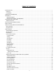
TABLE OF CONTENTS INTRODUCTION............................................................................................................................................................. 1 Definitions .................................................................................................................................................................... 1 Compatibility .................................................................................................................................
Select Keyboard Language .................................................................................................................................... 25 Security Configuration ............................................................................................................................................ 26 Keyboard Mapping.....................................................................................................................................................
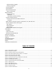
Figure 16- Port information- system structure.................................................................................................................................. 18 Figure 17- User login screen............................................................................................................................................................ 19 Figure 18- Administrator's main menu ............................................................................................................
NTI UNIMUX MULTI-USER KVM SWITCH INTRODUCTION The NTI UNIMUX-nXm-U (formerly referred to as ST-nXm-USBV-U) is a multi-user / USB KVM Switch, (n= number of users, m= number of CPUs). It allows multiple users (up to 8), each with USB user devices and monitor, to communicate directly with any WINDOWS, MAC and/or SUN USB CPU (up to 32) connected to the switch. These CPUs can be file servers, web servers, etc.
NTI UNIMUX MULTI-USER KVM SWITCH ORDERING INFORMATION The UNIMUX USB KVM switch is built to a specific size ranging from 2 to 8 users and 8 to 32 CPUs. The switch is built at the factory based on the specified size ordered. The switch has USB inputs and outputs that support all platforms and are configured with interface cables, see interface cable section. The “n” in the part number UNIMUX-nXm--U represents the number of users. Select either 2, 4, or 8 user switches.
NTI UNIMUX MULTI-USER KVM SWITCH 2 1 UNIMUX TM NTI R ESC USR 6 7 8 9 0 * MENU CPU 1 2 3 4 5 ENTER Network Technologies Inc Front View of UNIMUX FEATURES AND FUNCTIONS 1. Keypad- buttons for user control over switch functions 2. LCD - for visual indication of connection between the user and a specific CPU. 3. CPU x- USB Type B female connectors- for connection of CPU device cables 4. USB User Device x- USB Type A female connectors- for connection of user device cables 5.
NTI UNIMUX MULTI-USER KVM SWITCH Additional Features • A single CPU can be used by one or shared by several users. • Any USB type user device can control any USB CPU (Windows, MAC, and SUN platforms). • Power cycle circuit control allows the UNIMUX switch to be powered OFF, then ON, at any time without affecting the attached CPUs. (This assumes that the CPU supports hot plugging.) • Security features can be enabled on a user port by user port basis.
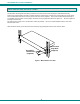
NTI UNIMUX MULTI-USER KVM SWITCH RACK MOUNTING INSTRUCTIONS This NTI switch was designed to be directly mounted to a rack and includes a mounting flange to make attachment easy. Install 4 cage nuts (supplied) to the rack in locations that line up with the holes (or slots) in the mounting flange on the NTI switch. Then secure the NTI switch to the rack using four #10-32 x3/4” screws (supplied).
NTI UNIMUX MULTI-USER KVM SWITCH INSTALLATION It is not necessary to turn OFF power to CPUs or monitors during this installation unless RS-232 is going to be connected. All cables, except for the RS-232 cables, may be hot plugged. If using RS-232 Control see RS-232 section on page 29 for more information. Observe normal precautions when connecting the RS232 cables to the CPU. Refer to the owner’s manual for the CPU being connected for precautions, if any. 1.
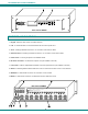
NTI UNIMUX MULTI-USER KVM SWITCH 2. Connect the user devices to the USB type A female ports labeled USB USER DEVICES on the rear of the UNIMUX switch. (See Figure 3.) Ensure that the monitors and related user devices are connected to ports having the same port numbers. (See Figure 5.) Note: If device cables are not long enough to reach the UNIMUX switch, they can be extended either 5 or 10 meters using either 1 or 2 NTI USB-A+A-5M Improved Active USB 5 Meter Extensions (purchased separately).
NTI UNIMUX MULTI-USER KVM SWITCH Ports for User 1 Connections Ports for User 2 Connections USER 4 USER 3 USER 2 NTI USER 1 R CPU 16 R S 2 3 2 MONITOR 3 MONITOR 1 MONITOR 4 MONITOR 2 Figure 5- Group user ports by like number Ports for CPU 1 Connections Ports for CPU 2 Connections CPU 3 CPU 2 CPU 1 VIDEO 3 VIDEO 1 VIDEO 4 VIDEO 2 Figure 6- Group CPU ports by like number 3.
NTI UNIMUX MULTI-USER KVM SWITCH USB Type B Female Connector CPU 1 Rear View of UNIMUX USER 4 USER 3 USER 2 USER 1 NTI R NETWORK 1275 Danner Dr Tel:330-562-7070 TECHNOLOGIES INCORPORATED Aurora, OH 44202 Fax:330-562-1999 www.nti1.
NTI UNIMUX MULTI-USER KVM SWITCH USING THE NTI UNIMUX USB KVM SWITCH Basic Operation The UNIMUX switch enables a user or several users to access any CPU at any time. A CPU can be shared so that more than one user can use a CPU and work on the same project – each from their own console. Resolution is 1900x1200 with no degradation – guaranteed. The front panel LCD indicates the port to which each user is attached.
NTI UNIMUX MULTI-USER KVM SWITCH OSD CONTROL OSD superimposes a menu system on the user’s video screen with a list of all connected CPUs. OSD allows CPUs to be named (with up to 12 character names). OSD then allows selection of CPUs by that name. Connected CPUs can be listed by name or by port number. OSD Search Mode enables the user to type in the first few characters of the CPU's name and the OSD will locate it. HELP screens assist with all OSD functions.
NTI UNIMUX MULTI-USER KVM SWITCH Initial startup When the UNIMUX is first powered ON, a splash screen similar to the following will appear: Press any key and the UNIMUX will connect you to the first CPU port with a connected CPU that is powered ON. To access Command Mode and connect to a different port or perform other user access functions (see below), press + <`> (accent/tilde key). User Access Functions Command Mode In order to control the switch with the keyboard, Command Mode must be enabled.
NTI UNIMUX MULTI-USER KVM SWITCH An arrow to the left of a port number in the list indicates the port the user is currently connected to. From left to right, the columns display the following: • Port Number User Cursor Power Status • Port Name Port Number • Power Status of the CPU (ON/OFF) Port Name Note: “NAC” indicates a non-accessible computer for that user Scroll Bar • The actual user number (1-8) connected to the CPU.
NTI UNIMUX MULTI-USER KVM SWITCH Function Keystroke Enter Find Mode, add a character to search string and select the CPU’s name that matches best. F Type any alphabetical or numeric character (A-Z, 0-9) Note: use is not case sensitive Switch to selected port Enter Logout (you will be prompted for confirmation) L Exit Command Mode Esc Figure 10- Administrator main menu Settings To enter the Settings menu (see Figure 11) press from the Command Mode menu.
NTI UNIMUX MULTI-USER KVM SWITCH OSD Settings The OSD Settings screen enables the user to adjust the height of the OSD screen on the monitor and the position of it. The position can be adjusted both horizontally, as well as vertically. Press from the Settings menu (above) to open the OSD Settings screen.
NTI UNIMUX MULTI-USER KVM SWITCH Scan Mode Using Scan Mode, the user can automatically switch from one CPU to another in predetermined configurable time intervals. The CPU ports to be scanned are easily selected provided the user has access to them. At initial startup, the user as access to all CPU ports by default. To activate or deactivate Scan Mode press from the Command Mode menu. The text shown in the menu (see Figure 10) will toggle between “Scan=N” and “Scan=Y”, each time the key is pressed.
NTI UNIMUX MULTI-USER KVM SWITCH Broadcast Mode To activate or deactivate Broadcast Mode press from the Command Mode menu. The text shown in the menu (see Figure 10) will toggle between “BCast=N” and “BCast=Y”, each time the key is pressed. When “BCast=Y” is shown, Broadcast Mode is active. When “BCast=N” is shown, Broadcast Mode is OFF. Broadcast Mode enables the user to type characters to more computers simultaneously.
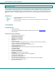
NTI UNIMUX MULTI-USER KVM SWITCH F3- Display Information To display information about a selected port, pressing the key from within the Command Mode main menu will cause a window to open (see below). The window will show the name of the port and its position in the system structure, level by level. This is most useful when cascading switches (see Cascading- page 35).
NTI UNIMUX MULTI-USER KVM SWITCH Security Enabling Security To enable the security feature the administrator must first enter Command Mode. If the Command Mode menu is not already displayed, press + <`> (accent/tilde key). The OSD menu will automatically appear on the monitor. To login as the administrator, the user must first logout by pressing , and then to confirm. A login prompt will appear.
NTI UNIMUX MULTI-USER KVM SWITCH User Login User Login Mode requires a user to login with a user name and password from the list created by the administrator. The user will only be able to login if security is enabled. With security enabled, the user will be locked to the current CPU and the login screen will remain on the monitor until the user logs in.
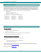
NTI UNIMUX MULTI-USER KVM SWITCH System Configuration To enter the System Configuration menu: press from the Administration menu. The System Configuration menu can only be accessed when the administrator is logged-in.
NTI UNIMUX MULTI-USER KVM SWITCH User Configuration To enter the User Configuration menu: press from the Administration menu. The User Configuration menu can only be accessed when the administrator is logged-in. The User Configuration screen lists the users configured to access the UNIMUX. Up to 63 users can be assigned access. To assign a user name, password, and port access control, select the user number or an empty record and press , , or click it with the mouse.
NTI UNIMUX MULTI-USER KVM SWITCH User Access Control To enter the Access Control list for a user, press A from the User Account screen for that user.
NTI UNIMUX MULTI-USER KVM SWITCH Idle Timeout The idle timeout is the amount of time that the administrator can be idle while in Command Mode before the administrator is automatically logged out. The idle timeout can be set to any value from 000 to 255 minutes. A value of 000 will disable it. After the idle timeout period has elapsed, the login screen will appear. To change the Idle Timeout setting, 1. press from the System Configuration menu (page 21) to display the 2.
NTI UNIMUX MULTI-USER KVM SWITCH Figure 29- Alternate Command Hot Key selection window Reset Port names To erase all configured port names and return them to the factory-default names, press from the System Configuration menu. After pressing the key, a confirmation message will appear. The administrator should press (Yes) to validate the selection or (No) to cancel it. Pressing will return to the Administration Mode menu. Power cycle the UNIMUX for the reset to take effect.
NTI UNIMUX MULTI-USER KVM SWITCH Security Configuration The UNIMUX can be configured to either have no security enabled such that any user can connect to the UNIMUX, or have security enabled such that a user must have a login name and password in order to enter Command Mode and make a connection with an accessible CPU. Only the administrator has access to Security Configuration.
NTI UNIMUX MULTI-USER KVM SWITCH Keyboard Mapping The keyboard configuration of each CPU is saved in the UNIMUX switch. For example, if the CPU attached to Port 4 had CAPS LOCK and NUM LOCK selected the last time that CPU was accessed, then they will automatically be set when that CPU is accessed again. Key Equivalents Using the chart below, find the character needed to be typed on the CPU being accessed, then follow the row across for the equivalent on the keyboard being used.
NTI UNIMUX MULTI-USER KVM SWITCH Esc ~ ` Num Lock Backspace Tab Enter Caps Lock Shift Shift Enter Ctrl Alt Ctrl Alt Typical 101 Keyboard Esc F1 F2 F3 F4 F5 F6 F7 F8 F9 F10 F11 ~ ` Print Screen SysRq F12 Scroll Lock Pause Break Num Lock Backspace Tab Enter Caps Lock Shift Shift Enter Ctrl Alt Alt Ctrl Windows Logo Key Application Key Windows Logo Key Windows Keyboard Power Button F1 esc F2 F3 F4 F5 F6 F7 F8 F9 F10 F11 ~ ` F12 delete help home pg up p
NTI UNIMUX MULTI-USER KVM SWITCH RS232 CONTROL RS232 enables the UNIMUX to be remotely controlled via RS232.
NTI UNIMUX MULTI-USER KVM SWITCH Wiring Schematic of Matrix-Y-1 cable 9D Male (Unit #1) 9D Female (Source) 2 9D Male (Unit #2) 3 3 3 5 5 5 2 2 7 8 1 4 6 Not connected to source connector Jumper Jumpers Figure 35- Pinout of Matrix-Y-1 cable 30
NTI UNIMUX MULTI-USER KVM SWITCH RS-232 Command Protocol Host controller commands supported by the unit are defined below.
NTI UNIMUX MULTI-USER KVM SWITCH Autostatus When Autostatus is enabled, any output-to-input connection change in the UNIMUX will cause an Autostatus message to be sent via RS232 to the administrator. The format of the message would be "pc SW,OP:IP" Example of an Autostatus message: pc 01,01:04 which means "At the switch with unit address 01, the user port 01 has changed connection to CPU port 04.
NTI UNIMUX MULTI-USER KVM SWITCH SerTest- RS232 Interface Test Program This software allows a user to test the functions of an NTI server switch, matrix switch or Multi-user/Multi-platform switch RS232 interface. The program SERTEST along with the Matrix Switcher's Control Program (page 32) is installed from the CD packaged with this switch.
NTI UNIMUX MULTI-USER KVM SWITCH RMTEST-RS232 Interface Test Program This software also allows a user to test the functions of an NTI server switch, matrix switch or Multi-user/Multi-platform switch RS232 interface. The RMTEST program is automatically loaded when installing the Matrix Switcher’s Control Program as described on page 32. The RMTEST program, located in the NTI program group, generates a main menu with the 3 selections described below: MAIN OPTIONS 1.
NTI UNIMUX MULTI-USER KVM SWITCH CASCADING The UNIMUX USB Matrix switch can be expanded to access up to 1024 CPUs by cascading multiple units together. As many switches as there are CPU ports may be connected to a UNIMUX USB Matrix switch. (See Figure 36) All downstream switches are referred to as "slaves" in a cascaded system. The only additional hardware required to cascade switches is a set of device and monitor cables for each “SLAVE UNIT” (see MATERIALS on page 2).
NTI UNIMUX MULTI-USER KVM SWITCH USER 1 USER 2 USER 3 USER 4 USER PORT UNIMUX-1X4 MASTER USER PORT UNIMUX-1X4 MASTER USER PORT UNIMUX-1X4 MASTER USER PORT UNIMUX-1X4 MASTER CPU PORTS CPU PORTS CPU PORTS CPU PORTS (TO USER PORT 2 ON SLAVES 1-4) (TO USER PORT 3 ON SLAVES 1-4) Users 5-8 only have access to CPUs 25-40.
NTI UNIMUX MULTI-USER KVM SWITCH REAR VIEW OF MASTER UNIMUX USER 4 USER 3 USER 2 NTI USER 1 R NETWORK 1275 Danner Dr www.nti1.
NTI UNIMUX MULTI-USER KVM SWITCH Operating Cascaded Switches Immediately after powering-ON the Master switch, the following splash screen will display on the monitor: All the downstream switches should be powered ON before pressing any key. If there are USB extenders connected, they should also be powered ON. An extra time of about 5 seconds after powering-ON the last unit may be needed to complete the USB enumeration process.
NTI UNIMUX MULTI-USER KVM SWITCH SAFETY STATEMENTS Grounding These products have protective earth ground terminals and are built with full attention to consumer safety. There must be an uninterruptible safety earth ground between the main power source and the product's power cord or supplied power cord set. If ever the possibility exists for the grounding protection to have been reduced in any way, disconnect the power supply until the grounding connection has been fully restored.
NTI UNIMUX MULTI-USER KVM SWITCH TROUBLESHOOTING Each and every piece of every product produced by Network Technologies Inc is 100% tested to exacting specifications. We make every effort to insure trouble-free installation and operation of our products. If problems are experienced while installing this product, please look over the troubleshooting chart below to see if perhaps we can answer any questions that arise.
NTI UNIMUX MULTI-USER KVM SWITCH INDEX Alternate command hot key, 24 Apple Mouse, 27 autologin, 26 Autostatus, 32 baud rate, 29 Broadcast Mode, 17 cables chart, 39 Cascading, 35 Change password, 23 devices supported, 1 edit user, 22 Find Mode, 15 forgot password, 19 front panel keypad, 10 fuse, 3 hot-plug, 4 idle timeout, 24 Installation, 6 Key Equivalents, 27 keypad, 10 Matrix Switcher's Control Program, 32 mounting in rack, 5 OSD, 11 Password and User Name, 19 port configuration, 21 reset port names, 25