GB USE AND MAINTENANCE MANUAL MISTBLOWERS TOWED MISTBLOWERS LASER - FUTURA - EXPO series AT STD/TOP - AT BASE Read this manual carefully before use.
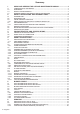
Summary 1 USING AND KEEPING THE USE AND MAINTENANCE MANUAL .................... 4 1.1 1.2 1.3 1.4 COMPOSITION OF THE MANUAL ....................................................................................... GUARANTEE ....................................................................................................................... PRODUCT RESPONSIBILITY .............................................................................................. WARNING SIGNS IN THE MANUAL AND ON THE MACHINE ..
6.2.3 6.3 6.4 6.4.1 6.4.2 ANTI-DRIFT NOZZLES ....................................................................................................... 20 CALIBRATING AXIAL FAN ATOMISERS ............................................................................. 20 CALIBRATING CANNON ATOMISERS ................................................................................ 21 TREATMENTS ON TALL PLANTS .......................................................................................
Thank you for having chosen UNIGREEN. The product you purchased has been designed and built with the greatest attention to the safety of the operator and the environment, nevertheless there are still some residual risks due to the nature of the product used. For this reason we recommend reading all of this manual to avoid making mistakes in the first period of use and to get the most out of the working life of the sprayer in time, doing the programmed maintenance at regular intervals.
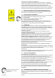
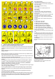
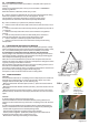
1 2 3 4 5 6 7 8 9 10 11 12 13 14 15 16 17 18 19 20 21 22 23 2 SAFETY REGULATIONS AND RESIDUAL RISKS In relation to safety, the following terms will be used: Dangerous zones: any zone inside and/or near the machine where the presence of a person exposed constitutes a risk for the safety and health of the same person. Person exposed: any person who has their body or any part of their body in a dangerous zone.
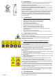
2.1 INTENDED USE The sprayer in this series is built for agricultural use. The materials used are resistant to normal chemical products used in agricultural spraying (or herbicides) at the time of construction. Any other use is not allowed and the manufacturer is not responsible for any damage caused by aggressive, dense or sticky chemicals.
Refer to the enclosed handbooks for the use and maintenance of the pump and pressure regulator and any accessories or motors. b) Please contact the agent in your zone, the nearest authorised workshop or UNIGREEN S.p.A. directly for any repairs the user feels they aren’t capable of performing alone. (see point 10.4) c) Due to the complexity of the equipment and the variety of technologies used (mechanical, hydraulic, oil-pressure and electrotechnical) operators must not dismantle or modify the equipment.
3.2 NOISE LEVEL OF THE MACHINE Use earmuffs to protect your ears when using the machine, below you will find the data on the maximum noise levels during work. Atomisers with axial fan rotor ACOUSTIC POWER LEVEL emitted by the machine with axial fan rotor: 113.5 and 118.5 dBA respectively in 1st and 2nd gear ACOUSTIC POWER LEVEL AT THE OPERATOR’S POSITION emitted by the machine with axial fan rotor: 89.0 and 89.
4.2 PRELIMINARY CHECKS When you receive the machine, check that it is complete and no parts are missing. If there are any damaged parts, inform your local reseller or UNIGREEN directly in good time. When the machine is delivered, make sure you ask: a) that the machine is delivered with all of its parts fitted and that the fitting meets the requisites in table N° 14b-15b-16b (pages 37, 38, 39).
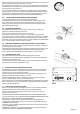
4.4 TRACTOR COUPLING = The tractor must be equipped with a 1”3/8 ASAE DIN 9611/A at 550 rpm power-takeoff capable of supplying the power necessary for operating the machine. = It must have a towing hitch (towed mistblowers with a towing eye or fork drawbar) and a three-point elevator (for mounted machines and a steering drawbar for towed machines) suitable for safely bearing the weight of the mistblower. = It must be able to tow the maximum overall mass of the machine.
4.5 CARDAN SHAFT In some models this is supplied on request. The cardan shaft must bear the CE mark. It must always have its own instructions that must be followed scrupulously and it should come with a cover bearing the mark, integrated in every part.
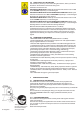
Before removing the cover of the filter, make sure that the same is isolated from the tubing by unscrewing the relevant rear valve (FIG. N°8) or on the 3way deviator (FIG. N° 10, page 14). After washing the cartridge, reassemble the cover making sure you connect the same to the circuit again, using the valves described above in the opposite order. WARNING!: Don’t disperse the washing residues in the environment!! Don’t use the sprayer without having consulted the enclosed handbook. way 4.
Pressure regulators without a volumetric valve (GCP3-way - GRH-RVA) Adjusting the maximum pressure valve = put main control A in the drain position (“OFF”). = loosen the hand wheel of maximum pressure valve B completely (anticlockwise).
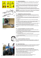
4.10 FILLING THE TANK The machines for defensive crop treatments, in consideration of the safety of persons, animals and the protection of the environment, must only be filled indirectly from open water courses and only by free-falling water from the waterworks. The pipe used for filling must never come into contact with the liquid inside the tank and therefore the water must always fall over the upper edge of the filling inlet and through the filter installed on it.
4.12 MIXING The active principle can be mixed using the relevant stirrers before and during the treatment. Correct mixing and stirring is the basis of the correct distribution on the crops. We recommend some useful accessories such as the premixer for powders and liquids (see the following paragraph). To mix the product in the tank proceed as follows: FIG. 13 a) high-pressure machines from 30 to 60 bar (FIG.
4.13 WASHING THE ATOMISER After every treatment, thoroughly clean the equipment, washing it with water inside and out. Dirty equipment is very dangerous for people and in particular for children. Discharging the residues of washing in the environment without taking precautions is forbidden as this pollutes water courses. Distribute the residues on the field or the crops where they won’t cause any damage. FIG. 17 P B At the end of the treatment, wash the circuit and the tank.
5 BLOWER GROUP All the mistblowers have a high speed fan rotor. You must take great care and beware of the effects that this can provoke: such as the aspiration and projection of foreign bodies which, although of a small size, can be very dangerous especially for the eyes and face. 5.1 AXIAL BLOWER GROUP WITH PULLEY The mistblowers that have a drive transmission between the pump and fan with pulleys are equipped with a neutral gear; the multiplied ratio is 1:4.
drilled reference disc (only fitted models) FIG. 20 5.4 AXIAL ROTOR Generally the new models of rotors are fitted with 7 vanes made of aluminium or nylon + fibreglass and the vanes have a variable inclination from 20° to 40° with step adjustment by 5° (in some cases there are drilled reference discs) FIG. 20. The angular movement of all of the vanes, if done correctly, doesn’t change the dynamic balance of the blower group.
5.6.4 OIL FEED FROM TRACTOR (for hydraulic systems) Connect the delivery and discharge quick-fit coupling to the respective connections, respecting the direction of flow. The distributor inlet pipe is connected to the aluminium flow separator valve next to the distributor. The flow separator must be adjusted correctly so it sends less than 4-5 L/1° to the distributor. To prevent the cylinders moving at a dangerous speed, adjust the relevant chokes near the cylinders.
6.2.2 LOW VOLUME CONICAL NOZZLES (150-500L/HA) Made of two ceramic pieces with colour-coded plastic inserts, they are available in various sizes identified by the colour (see table 3 page 34). They have been specifically designed to obtain a large number of small drops with strong turbulence even at low pressures (2-3 bar). This turbulence makes them suitable for penetrating luxuriant vegetation and so they are suitable for fungicides and insecticides.
6.4 CALIBRATING CANNON ATOMISERS ( Tables on pages 31-33 ) Atomisers with a cannon blower group are mainly intended for treating forest trees or other tall plants that it is impossible to drive into with the sprayer (for example tobacco or similar cultivations). They are also frequently used in cultivation under mobile greenhouses. When shooting the atomised chemical mix at distances, that can even be over 40 m, it isn’t possible to verify with the exact distribution on the area treated.
8 MAINTENANCE All of the maintenance operations and repairs must be carried out with the machine and cardan shaft stopped and the tank and circuit clean of any residues of chemical products. The maintenance of the mistblower is essential for maintaining a high level of safety. Also consult the single handbooks of the main components of the mistblower. 8.1 PROGRAMMED MAINTENANCE (TAB.
from our reseller perform any repairs or contact a specialised workshop. During all of the repairs, in particular when welding, the machine and the circuit must be clean of any residues of chemical product. If the machine has to be lifted (for example to change a wheel) follow the instructions in point 4.3 of the present handbook. Also make sure the machine is stopped, connected to the tractor, and use the relevant chocks to block the wheel still on the ground.
The decree imposes the limitation and elimination of several substances present in EEAW: lead, mercury, cadmium, chrome, hexavalent chrome, polybrominated biphenyl, polybrominated diphenyl and polybrominated diphenyl ethers. The machine has been designed and created in conformity with this directive. Follow the indications shown below. The symbol to the side, showing a barred garbage can on wheels, indicates the separate collection of the electrical and electronic apparatuses of the machine.
CALIBRATING TABLE TABLES FOR CALIBRATING MISTBLOWERS Ø500-600 unigreen spa Tabella erogazione in Litri/ettaro Gr.Ventola Ø500-Ø600 8 getti Lt.
CALIBRATING TABLE TABLES FOR CALIBRATING MISTBLOWERS Ø600-650 unigreen spa Tabella erogazione in Litri/ettaro Gr.Ventola Ø600-Ø650 10 getti Lt.
CALIBRATING TABLE TABLES FOR CALIBRATING MISTBLOWERS Ø700-750 unigreen spa Tabella erogazione in Litri/ettaro Gr.Ventola Ø700-Ø750 12 getti Lt.
CALIBRATING TABLE TABLES FOR CALIBRATING MISTBLOWERS Ø800 unigreen spa Tabella erogazione in Litri/ettaro Gr.Ventola Ø800 14 getti Lt.
CALIBRATING TABLE TABLES FOR CALIBRATING MISTBLOWERS Ø900 unigreen spa Tabella erogazione in Litri/ettaro Gr.Ventola Ø900 16 getti Lt.
CALIBRATING TABLE TABLES FOR CALIBRATING MISTBLOWERS Ø650 TGZ unigreen spa Tabella erogazione in Litri/ettaro Gr.Ventola Ø650 14 getti 14 GETTI Lt.
CALIBRATING TABLE for CANNONS TABLES FOR CALIBRATING CANNONS Ø450 unigreen spa Tabella erogazione in Litri/ettaro Cannone Ø450 2 getti Lt.
CALIBRATING TABLE for CANNONS TABLES FOR CALIBRATING CANNONS Ø400 - 440 - 480 unigreen spa Tabella erogazione in Litri/ettaro Cannone Ø400 6 getti + 2 laterali Lt.
CALIBRATING TABLE for CANNONS TABLES FOR CALIBRATING CANNONS Ø400 - 440 - 480 unigreen spa Tabella erogazione in Litri/ettaro Cannone Ø400 6 getti Testa Snodata Lt.
TABLE 1-3 TABLES OF DELIVERY OF NOZZLES FOR ATOMISERS TABLE OF DELIVERY IN LITRES / MIN. MEDIUM AND HIGH VOLUME Ø18 CONICAL NOZZLES FOR ATOMISER Ø NOZZLE Ø SLINGER PRESSURE TABLE.
TABLE 4-5 TABLES OF DELIVERY OF NOZZLES FOR HAND LANCES TABLE OF DELIVERY IN LITRES / MIN. OF THE CONICAL NOZZLES FOR LEVER LANCE note: standard Ø1,5 nozzle DIAMETER NOZZLE PRESSURE (BAR) TABLE.
TABLE 7 TABLE OF PROGRAMMED MAINTENANCE OPERATION 8h Check the level and state of the oil Check the accumulator pressure Check the suction (hoses, pipes, unions) Check and clean the suction and delivery filters Check the pump fixing feet and screws in general Check the diaphragm and the oil and change if necessary Check the suction/delivery valves Check the pump screws and bolts are tight Check and clean the nozzles and the non-drip diaphragm Check the wear of the nozzles Check the hydraulic oil level Che
TAB.14B ALLOWED FITTINGS 2004 TOWED ATOMISERS EXPO TYPE OF Polyethylene Tank MACHINE EXPO T - AT BASE TABLE 14 b FITTING FAN GROUP PUMPS COMET PUMPS ANNOVI REVERBERI PRESSURE REGULATOR JETS NOZZLES DRAWBAR OPTIONALS " " " " " " " " Nominal capacity (L.
TAB.15B ALLOWED FITTINGS 2004 TOWED ATOMISERS PLT TYPE OF Polyethylene Tank MACHINE LASER - FUTURA - AT STD/TOP TABLE 15 b P6 AT 6 STD FITTING FAN GROUP PUMPS COMET PUMPS ANNOVI REVERBERI PISTON PUMPS PRESSURE REGULATOR JETS NOZZLES DRAWBAR OPTIONALS Capacità nominale (lt.) FAN Ø600 NY. " " Ø600 ALU.
TAB.16B ALLOWED FITTINGS 2004 TABLE 16 b CANNON TOWED ATOMIS. TYPE OF Polyethylene Tank MACHINE LASER-FUTURA "C" ATC P6 P11 ATC6 ATC11 P16 ATC16 P20 ATC20 FITTING Nominal capacity (L.
Tel. +39 0522 369811 Fax. +39 0522 369898 e-mail: info@unigreen-spa.com internet: www.unigreen-spa.com member of the group Descriptions, indicative illustrations, UNIGREEN S.P.A. reserves the right to make variations or modifications without prior warning. UNI 16100006F - GB Sett-06 via Rinaldi, 105 - Loc.