
User`s guide


Appendix C-1
Twin-pump Systems Appendix C
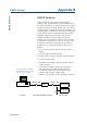
In each of the systems outlined in this manual there is a maximum of four pumps. The
signals from the controller to the pumps are carried on a communications channel
called the Gilson Serial Input Output Channel, or GSIOC for short. For a single pump-
ing system, all of the pumps are connected in parallel and the controller distinguishes
between any two pumps by a GSIOC identity number which you enter in the software.
Each pump must have a different GSIOC identity number.
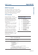
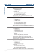
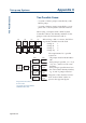
If we connect the pumps as shown in the following drawings, we have in effect two or
more parallel pumping systems. The same commands will go to each pump associated
with the same solvent, i.e. pumps A, and A’ will receive the same commands. Pump B
and B’ will receive the same commands etc. Each associated pump will operate in
exactly the same way, one being a mirror image of the other. In this way, we can create
two identical, parallel liquid streams with one controller. The hydraulic outlet tubing
can then be connected together to increase the overall flow rate. Theoretically there is
no limit to the number of pumps that can be connected in parallel, but effectively a
twin system with two liquid streams is the most practical. The advantage of this
arrangement is to be able to use a smaller head and hence work at a higher pressure.
For example, two 25SC heads could be used in parallel to obtain a flow rate of 50
mL/min. The maximum operating pressure would then be 28 MPa instead of a maxi-
mum of 14 MPa with a single 50SC head.
The actual flow rate of the combined pumps is the value programmed in the controller
multiplied by the number of pumps in parallel.