
User`s guide


2-4
Description 2
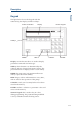
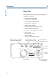
Rear View
The figure below shows a rear view of the 305 with
the electrical connectors. The function of each
connector is as follows:
• GSIOC TO SLAVE PUMP
Connection to a slave pump.
• GSIOC FROM CONTROLLER
Connection to a computer.
• PRESSURE CONTROL
Connection to the manometric module.
• INPUT/OUTPUT CONTROL
Connector for the 305 inputs and outputs.
• Power switch
On/off power switch.
• Power receptacle
Voltage selector and fuse holder.
Rear View
Power
switch
Power
socket
Fuse holder and
voltage selector
Input/Output socket
Pressure control
GSIOC socket, to be used
if the 305 is a slave pump
GSIOC socket, to be used if
the 305 is the Master pump
Fan opening