305 Pump User’s Guide
05 Piston Pump User’s Guide LT801152M/©2003 Gilson SAS All rights reserved September 2003
Table of Contents Safety 1 Introduction Using this Manual ........................................................................ 1-2 Unpacking ...................................................................................... 1-3 2 Description Front View ...................................................................................... 2-2 Keypad ............................................................................................ 2-3 Rear View ...........................................
File Selection ................................................................................. 4-22 Directory .................................................................................. 4-23 Copy ......................................................................................... 4-23 Delete ....................................................................................... 4-23 Edit/New ................................................................................ 4-23 Quit ............
Safety Read this section carefully before installing and operating the pump. For safe and correct use of the pump, it is essential that both operating and service personnel follow generally accepted safety procedures as well as the safety instructions given in this document, the 305 Pump User’s Guide. The instrument described in this document is 305 high pressure piston pump for use in single or multi-pump applications. It can control Gilson Model 306 slave pumps in multi-pump applications.
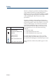
Safety However, adequate protection including clothing and ventilation must be provided if dangerous liquids are used. In case of incidental spillage, carefully wipe with a dry cloth, taking into account the nature of the spilled liquid and the necessary safety precautions.
Introduction 1 Gilson’s 305 Master pump conform to the standard specified in the ‘Declaration of Conformity’ certificate (reference LT801354) supplied with the instrument. The 305 Master pump is designed as a system controller. It can operate as a stand-alone isocratic pump or as a system controller, to deliver fluids (liquids or liquefied gas when specially equipped). As a system controller, the 305 Master pump controls a complete pumping system, elution pumps and injection pump.
1 Using this Manual Introduction 1-2 Using this Manual The 305 piston pump is a precision instrument which is simple and easy to use. To gain the maximum from the instrument, you should: • Read the description of the instrument in chapter 2. • Install the instrument as shown in chapter 3. • Follow the operating instructions given in chapter 4.
Introduction The 305 piston pump is packed in a single carton. Upon receipt of your instrument, carefully unpack the unit and inspect it for possible damage. This should be done immediately. Check the contents of the carton against the parts list to verify that all parts are included and undamaged. The parts list is given in Appendix A. Do this now, even if the unit will not be used immediately. Report any damage to the responsible carrier immediately.
Introduction 1-4 1
Description 2 This chapter describes the physical layout of the 305 piston pump. It describes the main body of the 305 and the position of the electrical connectors on the rear panel.
2 Description Front View Front view The figure below shows a front view of the 305 Master pump with a pump head mounted. There is a keypad which consists of a display, a numeric keypad and soft keys for programming the 305. The pump head is mounted on the right hand side.
2 Description Keypad Keypad The figure below shows the keypad with the numeric keys, the display and the soft keys. Power-on indicator Display Numeric keypad Softkeys PRIME HELP CANCEL ENTER Display: two 24-character lines are used to dispaly parameters commands and messages. Softkeys: their functions are determined by the software and may change from menu to menu. The present functions are displayed above each softkey.
2 Description Rear View Rear View The figure below shows a rear view of the 305 with the electrical connectors. The function of each connector is as follows: • GSIOC TO SLAVE PUMP Connection to a slave pump. • GSIOC FROM CONTROLLER Connection to a computer. • PRESSURE CONTROL Connection to the manometric module. • INPUT/OUTPUT CONTROL Connector for the 305 inputs and outputs. • Power switch On/off power switch. • Power receptacle Voltage selector and fuse holder.
Installation 3 This chapter describes how to install the 305 Master pump. It is recommended that you follow the installation instructions in the order that they are presented in the manual.
3 Electrical Installation - Power Installation Electrical Installation - Power For safety reasons, the 305 is shipped without the fuses installed and with the voltage selector in the 220/240 Volt position. You must: • Insert the correct fuses. • Set the voltage selector to your local voltage. Inserting the Fuses Ensure that the power cord is not connected before starting to install the fuses. Follow the procedure below to install the two fuses.
Installation Insert the fuse holder with the numbers 220/240 on the bottom, facing the small white arrow. For safety reasons, do not connect the power cord until you have finished assembling the instrument.
3 Mechanical Installation Installation Mechanical Installation This section explains how to install the pump head, the mast clamp and mast. The pump head and mast clamp for each pump should be installed before positioning the modules. Pump Head Installation The pump head is shipped in a hard case to protect it during transit. Unpack the pump head from its case and check that all of the parts are included. Follow the procedure below to install the pump head.
Installation Mechanical Installation Fix one clamp onto each pump in the system. After all the modules have been positioned, the stainless steel mast can be secured within the clamps. The lower end of the mast should be level with the bottom of the lowest pump.
3 Positioning the Modules Installation Positioning the Modules Before putting each module in position, make sure that each module is ready, i.e. that the fuses have been installed and that any mechanical installation is finished. The physical positioning of each of the modules in your system will depend on your type of system. Some suggested layouts are given below. These layouts have been desigend to make the hydraulic and electrical connections as simple as possible.
Installation This is a binary gradient system with two elution pumps, one injection pump, one manometric module, one mixer, one detector and one fraction collector. In this configuration, automatic injection is performed by the injection pump, located below the master pump. The pumping system consists of one 305 Master pump and two 306 slave pumps. The 305 Master pump should be the top pump. This makes the hydraulic connections to the manometric module as short as possible which gives the best results.
3 Installation Control Connections Control Connections After positioning all of the modules in the system, it is necessary to connect each module to the system controller. Two types of electrical connection must be made. • The manometric module must be connected to the 305 Master pump. • All of the slave pumps must be connected to the Master pump using the GSIOC cable provided.
3 Installation Control Connections looking at the rear of the 306 pumps and ensuring that the correct switch (2, 3 or 4) has been switched into the bottom position. The switches are labelled REMOTE, and are numbered 1 to 8 from left to right. Connecting the 305 to a 307 The 305 Master pump can directly control a 307 pump without the addition of a manometric module and with pressure display on the 305 screen.
3 Hydraulic Connections Installation 3-10 Hydraulic Connections The hydraulic connections for the 305 pump head are made using the tubing provided in the standard accessory package. Connect the 305 pump head input with the inlet tubing assembly provided with the pump head. The connections to the 305 pump head output should be made using stainless steel, titanium tubing or plastic tubing.
3 Installation Inputs Start/Stop Pause/Resume IN # 1 IN # 2 For coordination with surrounding equipment, electrical contacts are used. The input/Output connector is a 14-pin terminal block connector. Connections are made to the inputs and outputs using the connector supplied in the standard accessory package. Pin # Operation of the Inputs To activate an input, you must connect it to ground or 0 V.
3 Input/Output Connections Installation The Pause/Resume Input Mode Input Result Flow Closed Pause Flow Open Resume Flow after Pause Dispense Closed Pause Flow Open Resume Flow after Pause Program Closed Pause Program Open Restart Program The Pause/Resume input is used to pause and restart the 305 pump using an external contact. This input is only activated when the input changes from open to closed or from closed to open. The operation of each mode is shown in the table opposite.
3 Installation This input is activated when closed. Activating this input while Program mode is selected, causes File 13 to run. If nothing is programmed in File 13 or if File 13 is already running, this input will be ignored. This input can be used to start a special program if an external signal is received, for example a warning signal from a temperature measuring system.
Installation 3-14 3
4 Operation After switching ON the 305, the display shows the following information for one second: Model 305 VX.X Manometric Module: M805 This indicates the pump version, software version, VX.X, and the Manometric Module which is connected. If the Manometric Module is not properly connected, None is displayed. After this step, one of the Ready-to-Run screens is displayed.
4 Operation Priming the Pump Head Priming the Pump Head Do not run the pump when the pump head is dry. This can result in severe pump head damage. Check that the solvent bottle is filled with HPLC grade, degassed solvent or buffer. Immerse the inlet tubing filter into the solvent reservoir. Make sure that all of the hydraulic connections are properly made. Before priming, all electrical connections must be made, and all hydraulic connections in place.
4 Operation The keypad consists of numeric keys, dedicated keys such as Enter and Prime, 5 white soft keys and a 2 line 24 character display. The function of each part of the keypad is as follows. Numeric keys: Used to enter numeric values(to define parameters). PRIME: Runs the pump at maximum flow rate. HELP: Displays help messages. CANCEL: Cancels a value before it is entered into the memory. ENTER: Enter a value into the memory.
4 Setting Up the Pump Operation 4-4 Setting Up the Pump The software for the 305 Master pump can be explained with the help of the chart in Figure 15. The chart has 4 software branches. Pump: This is used to enter data about each pump in the system, this means pumps A, B, C and the Injection Pump, if present. I/O: This is used to define the Input/Output functions. File: This is used to write a method program. Mode: This is used to select the mode of operation.
4 Operation Setting Up the Pump With a new pumping system, you must enter data about each pump connected, i.e. Refill Time, solvent Compressibility and pump Head Size and Inlet Pressure. This is done using the Pump branch of the software. Data concerning the overall pumping system, for example high pressure limit, low pressure limit etc. is done using the I/O branch of the software. The File branch is used for writing files of method programs.
4 Setting Up the Pump Operation Pump A Refill time The refill time is the time required for the piston return stroke. Normally it is set at the lowest value (125 ms) to give the fastest refill time. If cavitation or degassing occurs, then a higher value must be used. The minimum value is 125 ms ( the default value) and the maximum value is 1000 ms. # The default value is 125ms. • Key in the refill time and press Enter. This brings the menu screen onto compressibility.
4 Operation This data is used to calculate the flow rate compensation for the compressibility of the solvent. The minimum value is 0 and the maximum value is 2000 Mbar-1. Compressibility values for commonly used solvents at atmospheric pressure are listed in Appendix E. The values for the most common solvents are: # The default value is 46 for water. • Key in the value for the solvent being used with pump A and press Enter.
4 Setting Up the Pump Operation A table of inlet pressure values for CO2 is shown below. Ambient temperature (°C) 15 20 22 25 30 31 (TC) Pressure P0 (MPa) 5.1 5.8 6.0 6.5 7.2 7.4 (PC) • Key in the desired inlet pressure according to the ambient temperature. • Press Enter. The four parameters for pump A are now entered. Entering the Parameters for Other Pumps in the System You must tell the 305 Master pump if the slave pumps B, C, and Inject are present in your system.
4 Operation Setting Up the Pump Input/Output Parameter Set Up (I/O) The I/O menu is used to enter data about parameters associated with the complete system. To go to the Input/Output parameter setup procedure: • press the Menu soft key • press the I/O soft key The sequence for defining parameters is: 1. High pressure limit. 2. Low pressure limit. 3. Alarm On/Off. 4. GSIOC ID number. 5. Output Contacts. 6. Pause/Program with or without flow. 7. Gradient profile selection. 8. Delay Volume selection. 9.
4 Setting Up the Pump Operation 4-10 This menu will not appear if there is no manometric module connected to the system. # The default value is 0. • Key in the value that applies to your system and press Enter.
4 Operation Setting Up the Pump Alarm The alarm is a buzzer which sounds every time there is an error or an invalid setting entered or encountered. It can be programmed to be either On or Off. This function only controls the operation of the buzzer, it does not affect the operation of the pump when there is an error. If the alarm is set to be On, the warning buzzer will sound every time an error is encountered. An error can be a pressure limit encountered, an invalid setting, or a pump absent.
4 Setting Up the Pump Operation Setting the outputs manually is useful to check that output # 1 turns on the integrator for example. However, when repeating the same operation many times, it is better to program the output operations as part of a method program. In this way, the outputs will follow the same sequence each time the method program is run. Refer to programming the outputs in Section 3 of this Chapter.
4 Operation Setting Up the Pump Delay Volume When the selected gradient profile is a solvent composition (%B for instance), the Delay Volume can be used to synchronise on the recorder the plot of the programmed profile with the plot of the detected profile (baseline drift). In this case the delay volume is generally defined, for a first approximation, as being the total volume between the mixer inlet and the detection cell inlet.
4 Setting Up the Pump Operation • Set the GSIOC ID number for the 305 Master pump. • Program outputs to be Open/Closed. • Set pause in program to be with or without flow . • Select the Gradient profile output to be Flow, %B, or %C. • Specify the Delay Volume. (Maximum value 999 mL) • Zero the Manometric Module. • When all I/O functions have been defined as required, press the Quit soft key. After entering the data about the pumping system, the pump is ready to run.
Operation Running the Pump in Flow Mode In Flow mode, the pump provides a constant flow rate, commencing when the Run soft key or start input is activated. The pump stops when the Stop soft key or stop input is activated. Mode Selection Mode Selection 4 To go to the Flow mode: • press the Menu soft key. • press the Mode soft key. • press the Flow soft key. This brings you to the Flow mode Ready-to-Run screen.
4 Mode Selection Operation • The pump will start either when the Run soft key is pressed, or when the start input is activated. • The pump will stop when the Stop soft key is pressed, or when the stop input is activated. Modifying the Flow Rate The flow rate can be modified at any time during a run by keying in a new value. It is possible to review and change the pump and I/O setup parameters except the pump head size during a run.
Operation In this mode the pump can be used to deliver a specified volume beginning when the Run soft key or start input is activated, and finishing when the specified volume of liquid has been delivered. The parameters to enter are dispense volume and dispense flow rate or time of dispense. Mode Selection Running the Pump in Dispense Mode 4 To go to the dispense mode : • press the Menu soft key. • press the Mode soft key. This brings you to the Dispense mode Ready-to Run screen.
4 Mode Selection Operation The maximum dispense flow rate depends on the Refill Time and Compressibility. If the parameters are not compatible with the dispense flow rate or volume entered, the message Invalid settings will flash on the screen after the Run soft key is pressed. In this case you must reduce the refill time or the flow rate. If the dispense flow rate or volume is not compatible with the head size, the software will not accept the value and you must key in a new value.
Operation 4 Mode Selection Operation of the Pressure Limits As a safety feature of the system, it is possible to define high pressure and low pressure limits so that the operation will stop when the system pressure falls outside these limits. If the high pressure limit is exceeded, for whatever reason (column clogged, wrong valve closed etc.), the pump will stop and the message High pressure limit will flash on the screen. The alarm will sound if it is programmed to be on.
Mode Selection Operation 4 If the pressure falls below the low pressure limit, the pump will stop and the message Low pressure limit will flash on the screen. The alarm will sound if it is programmed to be on. The pump will stay in this condition until the End soft key is pressed. The dispense mode can be simulated in the Program mode with the added advantage of having Safety Files (described page 4-31), and being able to program timed events.
Operation The 305 controls up to two other elution pumps and one injection pump through the GSIOC cable. Other instruments such as auto-samplers and fraction collectors can be connected to the 305 Master pump using the Input/Output contacts on the rear panel of the 305. Mode Selection At the end of a run in Program mode, the Solvent Consumption can be obtained by selecting the appropriate roll screen.
4 File Selection Operation File Selection One complete method is stored in a file. In order to read/edit/write a method, you have to go to a file. The sequence of screens and soft key command options for programming a file can be seen in the figure below. To go to a file: • press the Menu soft key. • press the File soft key. This brings you to the Select file menu. Key in the number of the file, for example 1, and press Enter.
Operation Press this key to go to each stored file, e.g. File 1, File 3 etc. This displays all of the files where method programs are stored. If no programs are stored, as in the case of a new pump, Select file # —will be displayed. Key in the file number that you want to use and press Enter. File Selection Directory 4 Copy Press this key to make a copy of a complete file. This is useful if you want to make a small modification to an existing program and keep a copy of the original program.
4 Programming a Method Operation Programming a Method A complete method program is written by programming flow rates, solvent compositions and operation of the outputs. The method program run time starts at time 0.00, i.e. when the start key is pressed, and ends at the time of the last timed event. For example, if you program the last event at time 20.00, then the run time is 20 minutes. You must program every event for your method, starting at time 0.00. For example, at time 0.
4 Operation Programming a Method If you link files together which have different values for the setup parameters, the pump will not start. After pressing Run the display will give you the message Note ! Setup has changed since file creation. Pressing Ok gives you the choice of which setup parameters to keep by asking the question Keep original setup ? Yes - No.
4 Programming a Method Operation The percentage of solvent A is calculated as: % solvent A = 100 - % B - %C. The example opposite is for a binary gradient. At 0 minutes, there is 95% solvent A and 5% solvent B. At 5 minutes, there is 80% solvent A and 20% solvent B. Example: There will be a linear gradient between two solvent composition points. With the example given, the %B will increase linearly from 5% to 20% in 5 minutes.
4 Operation • press the Add soft key to add a second timed event. • key in the time for the second flow rate, 5, and press Enter. • key in the second flow rate, 3, and press Enter. If you try to enter a flow rate value which is too high for the pump head, the entry is refused by the software. The maximum value accepted in a gradient system is the value of the smallest pump head size in the system. There will be a linear gradient between any two programmed flow rates.
4 Programming a Method Operation - Time at which the pump will wait for an input - Waiting for an open contact or a closed contact Example 4: 2.00 min Wait #1 Closed. To program this example: • press the Add soft key. • press the Wait soft key. • key in the time for the wait to begin, 2.00, and press Enter. • press the close soft key. The program waits at time 2.00 minutes until input #1 is closed. If input #1 is already closed at time 2.00 mins, the program will continue.
4 Operation 3.00 min Open Close Output 2 Pulse To program this example: • press the Add soft key. • press the Out soft key. • key in the time for the output to operate, 3.00, and press Enter. • key in the output number, 2, and press Enter. Programming a Method Example: Screen 1 Screen 2 The display will change to Open, Close or Pulse. • press the Close soft key. Inj In this menu you can injection a sample using the inject pump. There are three pieces of data for this menu.
4 Programming a Method Operation At the selected time, the Master 305 starts the injection pump and automatically lowers the elution rate in order to keep the total flow rate, and hence the pressure, constant. The following relationship is applied: F’e = F’e : Fe : Fi : Fe - Fi where the total elution flow rate during injection the total elution flow rate before injection the injection flow rate A stop-flow injection, generally desired, is then obtained by selecting Fi 암 Fe.
Operation The Safety Files are a useful safety feature which can be used to control the pumping system if a malfunction is detected. It is possible to detect if the system pressure is too high or too low, if there has been a power failure, or if an external sensor has File Name Function detected an illegal value (tempera11 Low File runs after a low pressure error ture too high, for example).
4 Programming the Safety Files Operation High Pressure Safety File (File 12) If the pressure goes above the high pressure limit, the sequence of events is as follows: • If the high pressure safety file (12) contains no program, the pumps stop at the instant the pressure rises above the limit. If the pressure drops below the limit again, the pump will restart. This cycle will continue indefinitely.
Operation • If there is a program stored in File 14: after the power is restored, the program in file 14 will be run. If there is a link to another program at the end of file 14, the linked file will start to run. If the alarm is on, it will sound. If there is a power failure in the Flow or Dispense modes, it has the same effect as if the pump was turned off and turned on again. The screen presented will be the Ready-to-Run Screen of the last used mode.
4 Running a Method Program Operation Running a Method Program At the end of programming the method and error files, the software returns to a Ready-to-Run Screen. The top left corner will indicate which Ready-to-Run screen you are in. To go to the Program mode Ready-to-Run Screen: • press Menu. • press Mode. • press Prog. The pressure can be displayed in 3 units, bar, MPa or kpsi. To change from one unit to another, press the soft key directly below bar. The units will change to MPa.
Operation After pressing Run, the display changes to give you the choice of Roll, Stop or Quit. Running a Method Program Press Run to start the conditioning of the column. The pump will ramp to the flow rate and solvent composition that is programmed in the time programmed. The values for time, flow rate and solvent composition can be changed during the conditioning. At the end of the ramp time, the flow rate and solvent composition will remain constant.
4 Running a Method Program Operation When the file is being run again, if any of these parameters has been changed, the following message will appear after Run has been pressed, Note! Setup has changed since file creation Ok. Press Ok. You can choose to keep the setup parameters which were stored with the method program or you can choose to keep the setup parameters which exist currently. Press Yes to keep the setup parameters which existed when the file was created.
Operation After a method program has finished, the display returns to the Ready-to-Run screen. Running a Method Program During a method run, the setup parameters and the method program can be modified. Modify a parameter in the same way that you program it. If the flow rate or composition is modified during a run, the new value will take effect from the instant it is programmed.
4 Programming Examples Operation Programming Examples Two example programs are given below. Before running these example programs, ensure that the hydraulic circuit is properly connected. Example 1 In the example given in List 1, the flow rate will start at 1 mL/min and increase to 4 mL/min after 2 minutes. The composition will be constant at 100% solvent A. An output will close at 0.00 minutes to start the integrator.
4 Operation Programming Examples Simple programs are given in list two and three for the Low pressure error file and the High pressure error file. In both programs, the flow rate is programmed to be 0 mL/min. This is a simple example of an error file. Enter these two error programs before running Example 1. After entering the two pressure error programs, the system is ready to run. Press Run. The display will look as opposite.
4 Programming Examples Operation Example 2 The operation of the method in Example 2 will be as follows. File # 4 contains the method program. The flow rate remains constant throughout the program. At 0.00 minutes the mobile phase will have a constant flow rate of 3 mL/min and a composition of 95% A, 5% B and 0% C. The composition will change to 70% A, 30% B and 0% C in a time of 1 minute. The composition will stay constant for 1 minute and then return to 95% A, 5% B and 0% C in a time of 0.5 minutes.
4 Operation Program List 4 Program List 5 Key to press Notes Key to press Notes Menu File Menu 3/ENTER New/Edit 3/ENTER 4/ENTER File # 3 Flow 0/ENTER 3/ENTER Add Enter the flowrate At 0.00 minutes Flowrate = 3mL/min Add the next timed event Mixt 0/ENTER 5/ENTER 0/ENTER Enter the composition At 0.00 minutes 5% solvent B 0% solvent C Add Mixt 1/ENTER 30/ENTER Add the next timed event Enter the composition At 1.
Operation 4-42 4
Maintenance and Troubleshooting 5 The 305 pump has been designed to require a minimum level of care and maintenance. In practice, maintenance is limited to cleaning and replacing parts of the pump head.
5 Maintenance and Troubleshooting Pump Head Maintenance Pump Head Maintenance The check valves and filters can be cleaned. Piston seals, check valves, piston assemblies, anti-extrusion gaskets and return springs should be replaced on a regular basis. A maintenance kit is available for each model of pump head. For details about maintenance kits and procedures, see the User’s Guide for your pump head. The time between each maintenance operation can be viewed by using the Info soft key in the Pump menu.
5 Maintenance and Troubleshooting Electrical Problems Problem Possible cause Solution Pump does not operate and power indicator does not light. Power cord unplugged. Fuse blown. Incorrect voltage setting. Check for power. See ‘Electrical installation’ in Chapter 3. Slave pump does not operate. GSIOC cable not connected or incorrectly connected. Check GSIOC cable is connected correctly to the socket on the 305. Incorrect GSIOC identity number. Check GSIOC identity number is set correctly.
5 Troubleshooting Maintenance and Troubleshooting Hydraulic problems Problem Possible cause Solution Leaks from the hole at the bottom of the pump head. Defective piston seal. Replace piston seal. Refer to User’s Guide for the pump head. Low flow rate. Leaks. Check for leaks. Plugged inlet filter. Clean or replace the inlet filter. Refer to User’s Guide for the pump head. Defective check valve. Clean or replace the check valve. Refer to User’s Guide for the pump head.
Accessory Parts List Appendix A Parts lists for the 305 Pump, consisting of Standard Accessories and Additional Accessories.
Appendix A Standard Accessory Parts List Accessory Parts List Standard Accessory Parts List Reference Qty Description 3645388 638314512 1 1 SC type pump head clamp Terminal block connector, 14 pin 36610101 6730204007 1 4 Double-ended wrench, 1/4"- 5/16" Fuses 2.0 Amp type “T” slow blow (5 x 20 mm) for 100-120 V 7080316105 6730104006 1 4 Power cord for 100-120 V Fuses 1.
Accessory Parts List Appendix A Reference Description 36078143 709910406 GSIOC cable Four-wire electrical cable, 1.7 m length, for I/O connections.* 03434939 2105703 Mast clamp Hex Mast, 3/4” x 16 mm * Several units may be required according to the system configuration.
Accessory Parts List Appendix A-4 Appendix A
GSIOC Control Appendix B This chapter explains how to control the 305 from a computer using Gilson HPLC system controller software.
Appendix B GSIOC Control GSIOC Features GSIOC Features GSIOC stands for Gilson Serial Input Output Channel. This communications channel links all of the Gilson modules in a system together. The system controller controls all of the modules in a system by sending GSIOC commands to the slave modules, for example pumps or detectors. Each device connected to the GSIOC channel is distinguished by a GSIOC identity number between 0 and 63.
Appendix B GSIOC Control GSIOC Commands GSIOC Commands The GSIOC commands can be used to control Gilson modules directly from a computer or from a Gilson HPLC system controller software package. The use of the GSIOC commands is completely detailed in the 305 technical manual. 305 Commands Specific 305 GSIOC commands consider the pump as a set of peripheral devices which can be either processed by the internal software, or by the GSIOC bus. There are two device types: input devices and output devices.
GSIOC Commands GSIOC Control Appendix B Immediate I Read Contact Inputs Response format: “abcd” where a is the START/STOP input, b is the PAUSE input, c is the IN#1 input and d is the IN#2 input. For each input: “C” if closed and disconnected from software, “c” if closed and disconnect from software, “D” if open and connected to software, “d” if open and disconnected from software. Response example: “DDCD” for IN#1 shorted to ground and all inputs connected to the internal software.
GSIOC Control Appendix B Read Contact Output Buffers Response format: “abcde” where a is the OUT #1 buffer, b is the OUT #2 buffer, c is the OUT #3 buffer, d is the HIGH pressure limit buffer, e is the LOW pressure limit buffer. For each input: “C” if closed and connected to software, “c” if closed and disconnected from software, “D” if open and connected to software, “d” if open and disconnected from software. Response example: “DDDDD” for all relays open and outputs connected to the internal software.
Appendix B GSIOC Commands GSIOC Control Buffered Q Enter Pressure Value Syntax: “QBxx.x” in bars, “QPx.xx” in MPa, or “QKxx.x” in kpsi. Parameter: if xxx is omitted, the pressure value is read from the manometric module and the pressure unit is selected for the immediate Q command. Command example: “QP1.23” for 1.23 MPa. Comment: this command does not affect the pressure unit on the display.
Appendix B GSIOC Control GSIOC Commands Identification of the master pump (pump A) is not critical. However, if a Model 305 is used with a computer-based Gilson system, its ID number must be cleaned in the Setup menu of the software package (Model 704, 712, 714 or 715). Command Examples Example 1: GSIOC Command - Zeroing the Manometric Module In order to zero the Manometric Module when controlling the 305 from a computer-based system controller, stop all pumps, or pause without flow.
Appendix B GSIOC Commands GSIOC Control Example 4: to restore display messages Command Comment (B) W0 Reconnect upper line to software. (B) W1 Reconnect lower line to software. This sequence sends “reconnect” commands to the internal software for the two related output devices. Original messages are restored. In the case where a separate access to the two lines of the display is not required, the same action is performed by a single command as above.
Twin-pump Systems Appendix C In each of the systems outlined in this manual there is a maximum of four pumps. The signals from the controller to the pumps are carried on a communications channel called the Gilson Serial Input Output Channel, or GSIOC for short. For a single pumping system, all of the pumps are connected in parallel and the controller distinguishes between any two pumps by a GSIOC identity number which you enter in the software. Each pump must have a different GSIOC identity number.
Appendix C Twin-pump Systems Two Possible Cases Two Possible Cases: - A system of mirror pumps controlled by a 305 Master pump. - A system of mirror pumps controlled by a computer and a Gilson System Controller software. When using a computer with a HPLC System Controller software, the identity numbers for the pumps can be chosen between 0 and 63.
Reference Informations Appendix D This chapter contains Table of Solvent Miscibility, Liquid Compressibility Values and Flow Rate Accuracy Principle.
Solvent Miscibility Table Reference Informations Appendix D Solvent Miscibility Table Miscibility means that solvents should mix with each other in all proportions. That solvents should be miscible is important both during elution and when switching from one solvent to another. You are advised to refer to the table, below, when selecting solvents.
Appendix D Reference Informations Bibliography Data The values of isothermal compressibility given below can be used for the Compressibility value in the pump setup menu. These values are given under athmospheric pressure (X0) and are expressed in Mbar-1. The opposite table refers to Handbook of Chemistry and Physics, CRC Press, 60th Ed. (1979).
Appendix D Liquid Compressibility Values Reference Informations Other Data Liquid Compressibility (Mbar-1) Acetonitrile 99 Tetrahydrofuran 93 Water-methanol, “ “ “ “ “ 10-90 (v-v) 20-80 “ 40-60 “ 50-60 “ 60-40 “ 80-20 “ 117 86 56 52 46 40 For other liquids currently used at ambient temperatures (20-25 °C), the following data is given. This data is a result of experiments done using the 305 pump, the figures are not presented as physical constants of scientific value.
Reference Informations To generate the selected flow rate with high accuracy, maintained under high pressure and for a variety of liquids, the 305 software adds to complementary corrections to the basic “piston flow rate”. Defined from the piston stroke volume only, the piston flow rate is theoretically accurate at athmospheric pressure only.
Flow Rate Accuracy Principle Reference Informations Appendix D-6 Appendix D The complementary compensation flow rate for all other factors, F2, is defined as the difference: F2 = F (F0 + F1) It was measured and the experimental results were expressed using a simple function of operating pressure P: F2 = f2 (a, b, P) Coefficients a and b were determined for each pump head. They are manufacturing constants attached to the parameter Head Size, a second ‘Setup’ parameter entered by the user.
305 Programming Sheet Appendix E The programming sheets provided on the next pages should be properly filled out prior to programming the pump. This wil ensure that the parameters are entered correctly, and will enable you to quickly cross check them when required.
Appendix E 305 Programming Sheet File Number Composition and Flow Method Name Set Up Parameters Pressure: High limit = Low limit = Number of pumps = Loops = Pump Model Solvent Units: %B Link file = I.D Refill Comp Head size Time (min) A B C Inj.
305 Programming Sheet Appendix E Example Appendix E-3
305 Programming Sheet Appendix E-4 Appendix E
Technical Data Appendix F The following information presents construction and operational characteristics for Gilson 305 Pumps.
Appendix F Type of Pump Technical Data Appendix F-2 Type of Pump Programmable reciprocating pump with singlepiston interchangeable head, constant stroke, and special fast-refill motion.
Appendix F Technical Data Working Range, Pump Heads and associated Manometric Modules A complete Gilson liquid delivery system includes up to four pumping modules with appropriate heads, a manometric module and a mixer for gradient elution. Pump head (model) 5SC 10SC 10WSC 10WTi 25WTi 25SC 50SC 100SC 200WTi Flow rate range* (mL/min) 0.010 0.050 0.050 0.050 0.125 0.125 0.250 0.500 1.000 - 5 10 10 10 25 25 50 100 200 Pressure range* (MPa) 0.1 0.1 0.1 0.1 0.1 0.1 0.5 0.5 0.5 - 60 60 60 60 28 28 14 7 3.
Appendix F Technical Data Working Range & Performance Data Liquid-contact Materials 316L stainless steel, titanium, sapphire/ceramic, ruby, PCTFE, PEEK, PTFE/HDPE. Binary Gradient Systems (two-solvent composition programming) Mean Accuracy Error < ± 3 % determinated in the range 0 - 10 % by 1 % steps and in the range 0 - 100 % by 10 % steps. Deviation from Linearity < ± 1 %. Repeatability < 1 % maximum imprecision for any composition.
Technical Data Operation Modes Constant flow rate (Flow), constant volume (Dispense), and timed-based sequence (Program) for up to four Gilson pumps controlled either by one 305 acting as a Master 305, or by an external computer. Control and Interfaces Control and Interfaces Appendix F Programmable Parameters Solvent composition points for high pressure mixing of 3 solvents from 3 pumps. Flow rate points that can be superimposed over gradient composition profile.
Appendix F Control and Interfaces Technical Data Appendix F-6 Electrical Interface 4 inputs, 3 programmable outputs. Digital Interface Gilson Serial Input/Output Channel. The pump can act as master or slave.
Technical Data Storage Indoor use only. Installation : Category II. Altitude: Up to 2000 m. Temperature range: 4 - 40 °C. Pollution degree 2. Environmental Conditions Environmental Conditions Appendix F Humidity: Up to 80 %. Power Requirements Frequency: 50 to 60 Hz. Voltage: 100 to 240 Vac. Power rating: 110 VA. Size and Weight Size (W x D x H): 330 x 330 x 150 mm. Weight: 10 kg (22 lb).
Technical Data Appendix F-8 Appendix F
World Wide Web: www.gilson.com E-mail: sales@gilson.com, service@gilson.com, training@gilson.com World Headquarters Gilson, Inc. 3000 W. Beltline Hwy., P.O.