Smartline Pump 1000 Manual / Handbuch V 7603 10/2007 Wissenschaftliche Gerätebau Dr. Ing. Herbert Knauer GmbH Hegauer Weg 38 D - 14163 Berlin, Germany Tel.: +49 (0)30 809 727 0 Fax.: +49 (0)30 801 50 10 E-Mail: info@knauer.net Internet: www.knauer.
CONTENTS Using this Manual Conventions in this Manual Importend Hint SOP´s in this manual General Description Setup of the Smartline Pump 1000 Unpacking Pump head identification Front View of the Smartline Pump 1000 Pump Head, Mixing Chamber; Capillary and Tubing Connections Rear Panel View of the Smartline Pump 1000 Connection to Main Power Control of the Smartline Pump 1000 Basics for operating the Smartline Pump 1000 Power On and Selftest Appearance of the Cursor Menu Structure of the Smartline Pump 1000
INHALT Hinweise zum Gebrauch des Handbuchs Konventionen in diesem Handbuch Wichtiger Hinweis SOP´s in diesem Handbuch Allgemeine Beschreibung Inbetriebnahme der Smartline Pump 1000 Auspacken Pumpenkopf Identifikation Frontansicht der Smartline Pump 1000 Pumpenkopf, Mischkammer; Kapillar- und Schlauchverbindungen Rückseitenansicht der Smartline Pump 1000 Netzanschluss Steuerung der Smartline Pump 1000 Grundsätzliches zum Betrieb der Smartline Pump 1000 Einschalten und Selbsttest Aussehen des Cursors Menüstru
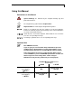
Using this Manual 3 Using this Manual Conventions in this Manual Special Warnings are indicated by the marginal warning sign and printed in bold letters. The marginal lamp symbol indicates helpful advice. Important Hints are marked by the marginal hand symbol. Arrows in an outlined form like this example used in block diagrams, indicate an automatic program run and change to the next line without the necessity of manual interventions.
4 Using this Manual SOP´s in this manual The Standard Operating Procedures (SOP) provided with this manual offer a convenient way of structuring complex tasks in the operation of your Smartline Pump 1000. They include step-by-step instructions leading the user through all routine tasks during operation. They can be used for documentation purposes and be copied, applied, signed, and filed in order to document the performance of the instrument.
General Description 5 General Description The Smartline Pump 1000 features a double-piston design with active pulsation dampening. Besides being able to deliver solvents with very low residual pulsation, the Smartline Pump 1000 is equipped with a new motor drive that provides for an extended lifetime and a low working temperature. The Smartline Pump 1000 is available with two kinds of pump heads, each equipped with either stainless steel, titanium or ceramic inlays: • • analytical pump head (0.001 – 9.
6 Setup of the Smartline Pump 1000 Setup of the Smartline Pump 1000 Unpacking Unpack the instrument and check the pump and accessories for any damage due to shipping. Make any claims for shipping damage to the transportation company responsible for shipping. Please check that the Smartline Pump 1000 is complete, using the “Packing List” as a guide at page 44. Should any article be missing, please contact our service department. Pump head identification The pump head is located behind the door.
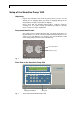
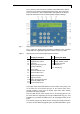
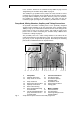
Setup of the Smartline Pump 1000 7 Fig. 2 shows the front view of the Smartline Pump 1000. On the door of the pump are the foil key touchpad and display panel. The pump head, pressure transducer, static mixing chamber and capillaries are located behind the front door and are therefore protected against damage. Fig. 3 Display panel and foil key touchpad in detail Fig. 3 shows the display panel and foil key touchpad of the Smartline Pump 1000. The explanation of position numbers is given in Table 2.
8 Setup of the Smartline Pump 1000 in the sections “Control of the Smartline Pump 1000“ on page 28 and “Programming the Smartline Pump 1000“ on page 21. The standby key {2.5} allows for the pump to be easily shut off as well as restarted. By pressing down on the standby key for more than 2 seconds, the pump will be completely shut down. Once the pump has shutdown, the standby key will light up and remain lit. The pump can then be restarted by again pressing on the standby key for more than 2 seconds.
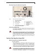
Control of the Smartline Pump 1000 9 Rear Panel View of the Smartline Pump 1000 5.6 Fig. 5 5.5 5.7 5.4 5.8 5.3 5.2 5.1 Rear Panel of the Smartline Pump 1000 5 5.1 Rear panel elements ON/OFF switch 5.5 5.2 Power connector 5.6 5.3 Serial number 5.7 5.4 Socket for optional connection 5.
10 Control of the Smartline Pump 1000 backflushing, follow the instructions given “Automatic piston Backflushing” on page 20. in the section Appearance of the Cursor The green arrow keys on the foil key touchpad can be used for positioning the blinking cursor on any field of the menu screen. The cursor appears as an underscore character while entering values (see Fig. 6, below). Refer to SOP 2 “Entering Data” on page 11 for guidelines on how to use the numeric keypad for data input (item {2.3} in Fig.
Control of the Smartline Pump 1000 11 Load Prog Link View rhombus Fig. 8 Edit Prog Clear 0 Links: (21 . . 29) Hold 0 Run 1 Flow [ml/min] 21 ___ Time [min] Pressure [0.1 Mpa] ___ ___ Events off 0 on 1 ___ ___ %A ___ ___ %B 2 ___ %C Setup GLP %D Example of a multi-page menu: VIEW menu Menus without a rhombus in the lower left corner of the display are single page menus. SOP 2 Entering Data This SOP applies to the Smartline Pump 1000 Firmware Version 1.0X or higher.
12 Control of the Smartline Pump 1000 The SETUP Menu The SETUP menu of the Smartline Pump 1000 enables access to the following features and functions: Hauptmenü Setup GLP GRADIENT MODE: none HPG D HPG C HPG B HPG A LPG PUMP HEAD: 10 ml 50 ml PRESSURE AUTOZERO Offset: 00.29 MPa FLOW: Adjust 4730 Correction 13.5% PRESSURE LIMITS [0.1 MPa] min: 000 max: 400 START INPUT: ENABLED DISABLED STOP Pump START Pump DATE: 26.07.03 dd.mm.yy TIME: 08.31.10 hh.mm.
Control of the Smartline Pump 1000 13 GRADIENT MODE: The Smartline Pump 1000 is capable of isocratic (none), high pressure gradient (HPG) and low pressure gradient (LPG) operation. The gradient mode can be selected by following SOP 3 “Selecting a Gradient Mode”. SOP 3 Selecting a Gradient Mode This SOP applies to the Smartline Pump 1000 Firmware Version 1.0X or higher. Use this SOP for selecting a gradient mode. 1. Select “GRADIENT MODE“ from the SETUP Menu. 2.
14 Control of the Smartline Pump 1000 By setting the minimum system pressure, damage to the pump caused by “running dry” can be avoided. When the system pressure is below the set limit, for example when a leak in the system is present, the pump will stop automatically after 30 seconds. By setting the minimum pressure limit to “0” the minimum system pressure will not be monitored. The absolute maximum pressure is limited by the pump head chosen and by the flow rate selected.
Control of the Smartline Pump 1000 15 Main menu Fig. 10 The VIEW menu with programs 1-4, 11 and link 21 Using the LINK Menu The LINK menu reports status information of the currently active program links. It is activated only if a link is running. Main menu Fig. 11 LINK menu without running link If a link is active, the menu shows the following structure: Main menu Fig. 12 LINK menu with running link In case a link is running, the first line of the menu gives the current status of the links.
16 Control of the Smartline Pump 1000 Using the GLP Menu The GLP menu reports statistical data for essential parameters of the Smartline Pump 1000. Fig. 13 gives an overview of the GLP menu. Main menu Setup GLP GLP: Total working time ♦ 003522 h 02 m 09 s GLP: Total pump cycles ♦ 210952 GLP: Last error codes ♦ 12 13 ERR 12 Date Time 13.01.03 16.21.33 ERR 13 Date Time 04.01.03 09.58.52 GLP: Installation date ♦ 15.06.03 GLP: Last service ♦ 00.00.00 code: 0 GLP: Power index ♦ 01511.
Operating the Smartline Pump 1000 17 Operating the Smartline Pump 1000 Before the pump can be put into operation, several settings must first be made from the menu screens. Use the information in the sections “Menu Structure of the Smartline Pump 1000” on page 10 and “Using the SETUP Menu” on page 13. Demonstration example for setting parameters For your convenience, this example points out how to configure a binary low pressure gradient using valves A and B.
18 Operating the Smartline Pump 1000 Load Prog Link Edit Prog Clear 0 Flow [ml/min] GRADIENT MODE: View Time [min] Events off 0 on 1 2 LPG ON Hold 0 Run 1 Fig. 14 Pressure [0.
Operating the Smartline Pump 1000 19 Faulty operation as well as a blockage in one of the capillaries can result in high pressure peaks. Moreover, we recommend setting the maximum system pressure at 25 Mpa when using ceramic inlays in the pump head in order to avoid damage to the pump. SOP 7 Setting the Flow Rate This SOP applies to the Smartline Pump 1000 Firmware Version 1.0X or higher. Use this SOP for setting the correct ow rate. SOP 8 1. Position the cursor over the FLOW field (see item {1.
20 Operating the Smartline Pump 1000 Fig. 15 Relation between event programming and the event terminal strip SOP 10 Start and Stop of Solvent Delivery This SOP applies to the Smartline Pump 1000 Firmware Version 1.0X or higher. SOP 11 1. Apply SOP 7 “Setting the Flow Rate” as described on page 19. 2. Use the START/STOP key (see item {2.1} in Fig. 3 on page 7)) to start and stop solvent delivery. Purging the Smartline Pump 1000 This SOP applies to the Smartline Pump 1000 Firmware Version 1.
Operating the Smartline Pump 1000 21 Automatic piston backflashing is effected over a rinsing pump which is installed inside of the Smartline Pump 1000. SOP 12 Preparing your Smartline Pump 1000 for automatic piston backflushing This SOP applies to the Smartline Pump 1000 Firmware Version 1.0X or higher. please connect the eluent tubing as follows: 1. Connect the silicone tubing from the accessory kit to position 1 and put the other end into the reservoir bottle (see Fig. 16 below).
22 Programming the Smartline Pump 1000 Programming the Smartline Pump 1000 Programs can perform the following actions: Control of ow rates Control of solvent compositions Output of control signals (Events) The Smartline Pump 1000 can store up to twenty programs with a maximum of 100 program lines in total. Up to nine links can be defined between existing programs. Features of Programs The time display units are shown in minutes with a decimal representation of seconds, i. e. 0.5 min = 30 sec.
Programming the Smartline Pump 1000 Load Prog A Link View 01 OFF 23 Edit Prog Clear 0 07 Hold 0 Run 1 Load Prog B Link View 01 OFF C Link View 01 OFF Edit Prog Clear 0 07 D Link View 01 OFF 001.0 000.00 Edit Prog Clear 0 %A 07 001.0 000.00 |200| 90 - - -.- %A Flow [ml/min] 07 _ _ _._ 020.0 %B %C %B %C Pressure Events [0.1 Mpa] off 0 on 1 %A %B %C Fig.
24 Programming the Smartline Pump 1000 During program execution the current solvent composition can be observed in the display fields % A and % B. At the end of the program the pump returns to the first line of the active program and continues pumping and the display will indicate ON in the lower left corner. SOP 15 Modifying and Deleting Programs This SOP applies to the Smartline Pump 1000 Firmware Version 1.0X or higher. Use this SOP for modifying and deleting programs. 1.
Programming the Smartline Pump 1000 Load Prog Link View 07 30 OFF Hold 0 Run 1 Fig. 18 Edit Prog Clear 0 25 Flow [ml/min] WAKE UP Time [min] Pressure Events [0.1 Mpa] off 0 on 1 P:01 on: 2 Setup at : 09 . 15 13 . 06 . 98 %A %B %C GLP %D Display of Wake-Up program 5. Execution of Wake-Up Program can be aborted by entering the number of another program. Example for creating a program Generation of program no. 7 with the following functions: Constant ow rate of 100.0 ml/min.
26 Programming the Smartline Pump 1000 1. From the EDIT PROG field, enter the program no. 20, specifically reserved for the emergency program. 2. Create the program 20 according to SOP 13 on page 22. 3. Start another program (for example, program no. 7 from SOP 16). 4. Create a connection between the ERROR IN and GND contact on the REMOTE terminal strip (see item {5.7} in Fig. 5) to produce an error signal. 5. Program no. 20 will then start automatically.
Programming the Smartline Pump 1000 Load Prog A Link View 27 Edit Prog Clear 0 01 L2 OFF Hold 0 Run 1 Load Prog B Link View Fig. 19 No** Pressure Events [0.1 Mpa] off 0 on 1 P-- Edit Prog Clear 0 R-- 2 Wait- Setup GLP Time [min] 01 L2 OFF Hold 0 Run 1 Flow [ml/min] Flow [ml/min] No01 No** %A %B %C Pressure Events [0.
28 Connecting the Smartline Pump 1000 to other Instruments Connecting the Smartline Pump 1000 to other Instruments Hydraulic Connections Make sure that all hydraulic connections are suitable to the system pressure and flow rate of your HPLC system. You can connect either a single solvent line or a low pressure mixing block to your instrument. Single Connection Solvent tubing is connected to the pump head according to part B of Fig. 20.
Connecting the Smartline Pump 1000 to other Instruments SOP 21 29 Connection of Inlet Manifold 1. Remove the pump head inlet bushing (4) and exchange it with the new one. Be sure to note the orientation of the check valve. This bushing also can be used without the inlet manifold. It enables by ist capillary connection the delivery of eluents with a certain primary pressure. 2. 3. 4. 5. 6. 7. Remove the lower right pump head set screw (2).
30 Connecting the Smartline Pump 1000 to other Instruments Fig. 23 Mounted SmartMix at the pumps front pannel Depending on the use in a HPG or LPG system opposit flow directions are necessary. For this purpose the mixer shall be turned by 180°, see Fig. 24. Injector HPG Pump 1 Pump 2 LPG Pump Fig. 24 System depending orientation of the SmartMix mixer SOP 22 Connecting the SmartMix mixer in a LPG system 1. Mount the SmartMix mixer as shown in Fig. 23. 2.
Connecting the Smartline Pump 1000 to other Instruments 31 Integrated Dynamic Mixing Chamber Optionally, your Smartline Pump 1000 can be fitted with an integrated dynamic mixing chamber (Fig. 25). The Smartline Pump S1000 with integrated dynamic mixing chamber is a special version of the S1000 pump. It is not possible to mount the dynamic mixing chamber into an older version of the pump. Fig.
32 Connecting the Smartline Pump 1000 to other Instruments 3. Disconnect the capillary of the chamber outlet, Pos. 6 in Fig. 25. 4. Loosen and remove the three mounting screws (Pos. 9) 5. Remove the upper chamber segment (Pos. 8). 6. According to your requirements, remove or install the intermediate chamber segment (Pos. 5). 7. Install the upper chamber segment and fix it with the three mounting screws.
Connecting the Smartline Pump 1000 to other Instruments 33 Connecting the EVENTS socket You can control the states of individual contacts of the EVENTS socket using SOP 9 “Setting the Control Signals (Events” on page 19. Specifications of the Event signals TTL (Transistor Transistor Logic) connections are to be connected only to TTL compatible outputs (max. consumption: 40 mA, UCEmax = 24 V) directed to GROUND.
34 Connecting the Smartline Pump 1000 to other Instruments 50ml head. The cables to which the REMOTE and EVENT terminal strips are connected can, under certain circumstances, be subject to electromagnetic disturbances. Such disturbances can be effectively suppressed with the enclosed ferrite ring. If necessary, the ferrite ring should be attached to the cable to which both terminal strips are connected (see Fig. 28 below). Fig.
Connecting the Smartline Pump 1000 to other Instruments Fig. 29 35 Connection scheme of three Smartline Pumps 1000 For connection with a PC you will need the Y-shaped cable which is included with the ChromGate® or EuroChrom® software/hardware packages. You may also include other network integrateable KNAUER instruments, such as the KNAUER interface box. Also simple ASCII codes are able to control the pump. ESC sequences are not needed. Thus, a simple terminal program may be used.
36 Connecting the Smartline Pump 1000 to other Instruments Table 5 Communication example for the 10 ml pump head Input Reply Description ST 2 OK Set the flow rate to 2 ml/min Command correctly understood and executed ST 2.200 OK Set the flow rate to 2.200 ml/min Command correctly understood and executed ST 10 ? Set the flow rate to 10 ml/min Command not understood. Flow rate remains at 2.
Simple Maintenance 37 Simple Maintenance You may carry out maintenance and cleaning procedures only on the pump head and on the optionally integrated dynamic mixing chamber. Both pump heads (10 ml and 50 ml) are identical and differ only in their size, therefore the descriptions below are valid for both sizes of pump heads with stainless steel, titanium, or ceramic inlays.
38 Simple Maintenance 2. The “Piston rods”, item {3.17} in Fig. 30, may be removed using pliers. Grasp the tip of the piston using the pliers and pull it out carefully in a straight line. If the rods are broken, you must check the entire pump head for damage. SOP 29 Disassembling the pump head All position numbers of the items described refer to Fig. 30. 1. Apply SOP 28 “Removing and checking piston rods”. 2. Loosen the two retaining plate screws (item {3.
Simple Maintenance 39 3.3 3.4 3.5 3.6 3.10 3.10a 3.11 3.11a 3.12 3.13 3.14 Fig. 30 Pump head screws Housing Bushing, inlet Bushing, outlet Check valves, inlet and outlet Distance holder Piston seal, high pressure Piston seal, low pressure Seal holder (titanium) Pressure plate Spacing bolts 3.15 3.17 3.18 3.19 3.20 3.21 3.22 3.23 3.
40 Simple Maintenance 3. With the open side facing downwards, press the new piston seals (item {3.11}) carefully into the seal holder, making sure to keep the seal straight. 4. Lock the seal holder in place by attaching the check valves (item {3.10}) and distance holder (item {3.10a}) according to SOP 33 “Cleaning check valves” on page 41. 5. Place the O-rings (item {3.21}) on the inner side of the pressure plate (item {3.13}). 6. Install the pressure plate (item {3.13}).
Simple Maintenance SOP 32 41 Replacing check valves Remove the connection from the pump head to the solvent reservoir. SOP 33 1. Remove the bushing on the inlet side (item {3.5}). The lower check valve (item {3.10}) can now be removed together with the bushing. 2. Remove the complete capillary connection (item {3.22}) between the two pump chambers. Loosen the screw fittings by alternating from one to the other, to avoid bending the capillary. 3. Remove the bushing from the outlet side (item {3.
42 Simple Maintenance 6. Put the check valves into the bushing holes on the pump head. Orient the check valves according to the flow direction required for that position. Screw in the bushings by hand. Tighten the bushings carefully with a spanner by about 1⁄2 - 3⁄4 turns. To avoid destruction of the ceramic seal holders, tighten the screws of the ceramic seal holder (item {3.5} and {3.6}) with 8 Nm using a torque wrench. Dynamic Mixing Chamber The dynamic mixing chamber is nearly maintenance-free.
43 List of Display Messages The following list shows messages that may appear on the main screen of the Smartline Pump 1000 and the pages of this manual on which they are described.
44 Packing List Packing List The Smartline Pump 1000 will be delivered together with one of the following pump heads: 10ml pump head: order number A50303 with stainless steel inlays order number A50301 with titanium inlays order number A50302 with ceramic inlays 50ml pump head: order number A50313 with stainless steel inlays order number A50311 with titanium inlays order number A50312 with ceramic inlays The delivery consists of:: ● Smartline Pump 1000 basic unit with pump head installed Manual ● Power s
Spare parts and accessories 45 Spare parts and accessories Pump heads KNAUER order number Pump head, 10ml, with stainless steel inlays A54103 Pump head, 10ml, with titanium inlays A54101 Pump head, 10ml, with ceramic inlays A54102 Pump head, 50ml, with stainless steel inlays A54113 Pump head, 50ml, with titanium inlays A54111 Pump head, 50ml, with ceramic inlays A54112 Cables Power supply cable, 230V M1479 RS-232 cable A0895 Set WAGO connecting rails A1402 Set signal conductors A1467
46 Technical Data Technical Data Delivery system Double-piston pump with main and auxiliary piston Automatic piston backflushing standard Flow Rate range 10 ml pump head 50 ml pump head 0.001– 9.999 ml/min at external control 0.01 – 50 ml/min Flow accuracy < 0.5%, at 1ml/min, 12 MPa Flow precision < 0.1%, at 1ml/min, 12 MPa Residual pulsation < 0.5% at 1ml/min methanol : water (8:2), 12 MPa, System protection Soft start, Pmin und Pmax adjustable Max.
Hinweise zum Gebrauch des Handbuchs 47 Hinweise zum Gebrauch des Handbuchs Konventionen in diesem Handbuch Besondere Warnhinweise und Hinweise auf mögliche Probleme sind mit dem Warnsymbol gekennzeichnet. Ein nützlicher Tip wird in der Marginalspalte durch das Symbol hervorgehoben. Wichtige Hinweise werden in Hinweissymbol kenntlich gemacht. der Marginalspalte durch das Die Bezüge zu Details in Abbildungen im Text dieses Handbuchs werden durch das Format wie z.B.: „siehe Pos. {3} in Abb.
48 Hinweise zum Gebrauch des Handbuchs SOP´s in diesem Handbuch Die Standardarbeitsanweisungen (Standard Operating Procedures, SOP) dieses Handbuches ermöglichen die Strukturierung zusammenhängender Aufgaben beim Betrieb Ihrer Smartline Pump 1000. Sie beinhalten schrittweise Anweisungen, die den Anwender durch alle Aufgaben führen. Sie können gleichfalls zu Dokumentationszwecken genutzt werden.
Allgemeine Beschreibung 49 Allgemeine Beschreibung Herausragendes Merkmal der Smartline Pump 1000 ist die Doppelkolbentechnik, gekoppelt mit der elektronischen Pulsationsdämpfung, die eine Flüssigkeitsförderung mit niedriger Pulsation und hoher Flusskonstanz ermöglicht. Der neue Antrieb der Smartline Pump 1000 zeichnet sich durch lange Lebensdauer und geringe Arbeitstemperatur aus.
50 Inbetriebnahme der Smartline Pump 1000 Inbetriebnahme der Smartline Pump 1000 Auspacken Alle KNAUER-Geräte werden ab Werk sorgfältig und sicher für den Transport verpackt. Prüfen Sie dennoch nach dem Auspacken alle Geräteteile und das Zubehör auf mögliche Transportschäden und machen Sie gegebenenfalls Schadensersatzansprüche sofort beim Transportunternehmen geltend. Bitte überprüfen Sie gemäß Abschnitt „Lieferumfang“ auf Seite 90 das Zubehör auf Vollständigkeit.
Inbetriebnahme der Smartline Pump 1000 51 Frontansicht der Smartline Pump 1000 Abb. 2 Frontansicht der Smartline Pump 1000 Abb. 2 zeigt die Vorderseite der Pumpe Smartline 1000. Auf der Tür der Smartline Pump 1000 sind die Bedientasten und die DisplayInformationen angeordnet. Pumpenkopf, Druckaufnehmer, statische Mischkammer sowie Kapillaren befinden sich hinter der Tür und werden somit leichter vor Beschädigungen bewahrt. Abb. 3 Display und Folientastatur In Abb.
52 Inbetriebnahme der Smartline Pump 1000 Tabelle 2 Erläuterung der Bedienfeldpositionen 1 Displayinformation 2 Folientastatur 1.1 1.2 1.3 1.4 Zu ladendes Programm Zu editierendes Programm Flussrate Systemdruck oder |eingestelltes Druckmaximum| 2.1 2.2 2.3 2.4 2.5 Pumpe START / STOP Spülen START / STOP Numerische Folientasten Pfeiltasten Standby Taste 1.5 1.6 1.7 1.8 1.9 1.
Inbetriebnahme der Smartline Pump 1000 53 optional 6.1 3 3.1 3.2 6.3 4.4 4.2 4.3 Pumpenkopf Kapillarverbindung Montageschrauben 4.1 4.5 3.8 3.7 3.5 4 4.1 4.2 3.4 3.3 3.2 3.6 3.1 Druckaufnehmer Druckaufnehmereinlass Entlüftungskapillare, Purge Auslass Entlüftungsschraube Eluentenauslass zur Säule Einlassventilverschraubung 4.3 Eluentenauslass zum 4.4 Druckaufnehmer 4.5 Schlauchführung 3.5 Kapillare zum Druckaufnehmer 6 Mischkammer 3.6 Auslassventilverschraubung 6.1 Auslassanschluss 3.
54 Steuerung der Smartline Pump 1000 Rückseitenansicht der Smartline Pump 1000 5.6 Abb. 5 5.5 5.7 5.4 5.8 5.3 5.2 5.1 5 Rückfrontelemente 5.1 5.2 5.3 ON/OFF Schalter Netzanschluss Seriennummer 5.5 5.6 5.7 RS232 Interfaceanschlüsse Anschlussleiste Events Anschlussleiste Remote 5.4 Anschluss für optionalen Smartline Manager 5000 5.
Steuerung der Smartline Pump 1000 55 Lassen Sie die Smartline Pump 1000 niemals ohne Flüssigkeit im Pumpenkopf sowie in der Kolbenhinterspülung laufen. Andernfalls kann der Pumpenkopf beschädigt werden. Um die Kolbenhinterspülung einzurichten, folgen Sie der Anweisung “Kolbenhinterspülung” auf Seite 65. Aussehen des Cursors Verwenden Sie die grünen Pfeiltasten der Tastatur, um den blinkenden Cursor auf die gewünschte Position des Display-Menüs zu bringen.
56 Steuerung der Smartline Pump 1000 4. Wählen Sie die Raute und drücken Sie die ¾ oder ½ Taste, um wieder zum Hauptmenü zu gelangen. Load Prog Link View Raute Abb. 8 Edit Prog Clear 0 Links: (21 . . 29) Hold 0 Run 1 Flow [ml/min] 21 ___ Time [min] Pressure [0.1 Mpa] ___ ___ Events off 0 on 1 ___ ___ %A ___ ___ %B 2 ___ Setup GLP %C %D Beispiel eines mehrseitigen Menüs: VIEW Menü Menüs ohne Raute bestehen aus nur einer einzelnen Seite.
Steuerung der Smartline Pump 1000 57 Das SETUP-Menü Das SETUP-Menü der Smartline Pump 1000 (Abb. 9) ermöglicht den Zugang zu folgenden Parametern und Funktionen: Hauptmenü Setup GLP GRADIENT MODE: none HPG D HPG C HPG B HPG A LPG PUMP HEAD: 10 ml 50 ml PRESSURE AUTOZERO Offset: 00.29 MPa FLOW: Adjust 4730 Correction 13.5% PRESSURE LIMITS [0.1 MPa] min: 000 max: 400 START INPUT: ENABLED DISABLED STOP Pump START Pump DATE: 26.07.03 dd.mm.yy TIME: 08.31.10 hh.mm.
58 Steuerung der Smartline Pump 1000 GRADIENT MODE: Die Smartline Pump 1000 kann isokratisch (none), mit einem Hochdruckgradienten (HPG) und einem Niederdruckgradienten (LPG) arbeiten. So können Sie den Gradienten-Modus auswählen: SOP 3 Wahl eines Gradienten-Modus Diese SOP gilt für die Smartline Pump 1000 Firmware Version 1.0X. Verwenden Sie diese SOP zur Festlegung des Gradienten-Modus. 1. Wählen Sie im SETUP Menü „GRADIENT MODE“ aus. 2. Wählen Sie den gewünschten Operationsmodus (HPG/LPG) aus. 3.
Steuerung der Smartline Pump 1000 59 PRESSURE LIMITS: Hier können Sie die Einstellung des minimalen und maximalen Systemdrucks vornehmen. Die Pumpe stoppt automatisch, wenn die eingestellten Grenzen überschritten werden. Mithilfe des minimalen Systemdrucks kann das Trockenlaufen der Pumpe verhindert werden. Unterschreitet der Systemdruck, z.B. aufgrund einer Leckage, den eingestellten minimalen Druck, so schaltet sich die Pumpe nach 30 sec automatisch ab.
60 Steuerung der Smartline Pump 1000 Das VIEW-Menü Dieses Menü (View = Anschauen) listet vorhandene Programme und Programmverknüpfungen auf. Ein Beispiel ist in Abb. 10 wiedergegeben. Hier wurden die Programme 1, 2, 3, 4, 11 und Link 21 erstellt. Hauptmenü Abb. 10 Das VIEW-Menü mit den Programmen 1-4, 11 und Link 21 Das LINK-Menü Im LINK-Menü können Sie sich über den aktuellen Status aktiver Programmverknüpfungen (Links) informieren. Es kann nur aktiviert werden, wenn gerade ein Link abläuft. In Abb.
Steuerung der Smartline Pump 1000 61 Das GLP-Menü Das GLP-Menü zeigt statistische Daten wichtiger Parameter der Smartline Pump 1000. Abb. 13 gibt einen Überblick des GLP-Menüs. Eine Übersicht über die möglichen Fehlercodes ist im Abschnitt „Liste der Displaymeldungen“ auf Seite 89 zu finden. Hauptmenü Setup GLP GLP: Total working time ♦ 003522 h 02 m 09 s GLP: Total pump cycles ♦ 210952 GLP: Last error codes ♦ 12 13 GLP: Installation date ♦ 15.06.03 GLP: Last service ♦ 00.00.
62 Bedienung der Smartline Pump 1000 Bedienung der Smartline Pump 1000 Vor Inbetriebnahme der Pumpe müssen mehrere Einstellungen vorgenommen werden. Die erforderlichen Informationen entnehmen Sie bitte den Abschnitten „Menüstruktur der Smartline Pump 1000“ auf Seite 55 und „Das SETUP-Menü“ auf Seite 57.
Bedienung der Smartline Pump 1000 Load Prog Link Edit Prog Clear 0 63 Flow [ml/min] GRADIENT MODE: View Time [min] Events off 0 on 1 2 LPG ON Hold 0 Run 1 Abb. 14 Pressure [0.
64 Bedienung der Smartline Pump 1000 2. Geben Sie den gewünschten Wert ein. Der eingestellte Wert ist durch zwei vertikale Linien markiert, die ihn als Eingabewert kennzeichnen, siehe auch Abb. 6 auf Seite 55. Gemessene Druckwerte werden ohne diese Linien dargestellt. 3. Drücken Sie eine beliebige Pfeiltaste zur Bestätigung der Eingabe und neuen Auswahl. Fehlbedienungen sowie Verstopfungen von Kapillaren können hohe Druckspitzen verursachen.
Bedienung der Smartline Pump 1000 3. 65 Beenden Sie die EVENT Eingabe durch Drücken einer Pfeiltaste. Abb. 15 Beziehung zwischen Event-Programmierung und –Anschlussleiste SOP 10 Starten und Stoppen der Lösungsmittelförderung Diese SOP gilt für die Smartline Pump 1000, Firmware Version 1.0X. SOP 11 1. Verfahren Sie nach SOP 7 „Einstellung der Flussrate“ auf Seite 64. 2. Verwenden Sie die START/STOP Taste, siehe Pos. {2.1} in Abb.
66 Erstellung von Programmen mit der Smartline Pump 1000 Die automatische Kolbenhinterspülung erfolgt über einer Spülpumpe, die in der Smartline Pump 1000 installiert ist. SOP 12 Installation der Verbindungen der automatischen Kolbenhinterspülung in die Smartline Pump 1000 Diese SOP gilt für die Smartline Pump 1000. Schließen Sie bitte die Verbindungen wie folgt an: 1. Verbinden Sie mithilfe der Silikonschläuche aus dem Beipack die Position 1 mit dem Vorlagebehälter (Abbildung 16).
Erstellung von Programmen mit der Smartline Pump 1000 67 beliebigen Programms an dem Errorsignal Eingang an der Smartline Pump 1000 ein Kurzschluss angelegt, so wird das Notprogramm (Programm 20) automatisch gestartet, soweit das Programm 20 vorher programmiert worden ist. Eigenschaften von Programmen Die Zeitanzeige wird in Minuten mit dezimaler Teilung der Sekunden vorgenommen, d.h. 0,30 min = 18 s.
68 Erstellung von Programmen mit der Smartline Pump 1000 Load Prog A Link View 01 OFF Edit Prog Clear 0 07 Hold 0 Run 1 Load Prog B Link View 01 OFF C Link View 01 OFF Edit Prog Clear 0 07 Edit Prog Clear 0 07 D Link View 01 OFF Hold 0 Run 1 %A %B %C 001.0 000.00 |200| 90 Flow [ml/min] - - -.Time [min] Flow [ml/min] 07 _ _ _._ 020.0 Time [min] 2 |200| 0 0 0 0 0 0 0 0 100 0 Pressure Events [0.1 Mpa] off 0 on 1 ***.* Edit Prog Clear 0 Pressure Events [0.
Erstellung von Programmen mit der Smartline Pump 1000 69 verfolgen. Am Ende des Programms kehrt die Pumpe zur ersten Zeile des aktiven Programms zurück und pumpt kontinuierlich weiter. Auf dem Display unten links erscheint wieder ON. SOP 15 Programme ändern und löschen Diese SOP gilt für die Smartline Pump 1000 Firmware Version 1.0X. Verwenden Sie diese SOP zum Ändern und Löschen von Programmen. 1. Geben Sie die Nummer des zu ändernden Programms in das Feld Edit Prog ein. 2.
70 Erstellung von Programmen mit der Smartline Pump 1000 Load Prog Link View 07 30 OFF Hold 0 Run 1 Abb. 18 Edit Prog Clear 0 Flow [ml/min] WAKE UP Pressure Events [0.1 Mpa] off 0 on 1 P:01 on: Time [min] 2 Setup at : 09 . 15 13 . 06 . 98 %A %B %C GLP %D Display des Wake-Up Programms 5. Sie können die Ausführung des Wake-Up-Programms durch Eingabe einer anderen Programmnummer abbrechen.
Erstellung von Programmen mit der Smartline Pump 1000 SOP 17 71 Ausführen des „Notprogramms“ Die Verwendung eines Notprogramms ist dann empfehlenswert, wenn die Pumpe für längere Zeit z. B. über Nacht unbeobachtet in Betrieb ist. Bei Auftreten eines ERROR-Signals kann das aktivierte Notprogramm beispielsweise mit einem Abschalten der Pumpe reagieren. Diese SOP gilt für die Smarlline Pumpe 1000 Firmware Version 1.0X oder höher. 1.
72 Erstellung von Programmen mit der Smartline Pump 1000 Bei der Einstellung Wait = 1 wartet die Pumpe auf ein externes Startsignal oder darauf, dass der Anwender die Zifferntaste 1 drückt, bevor diese Zeile abgearbeitet wird. Bei der Einstellung Wait = 0 werden die Programmschritte des Links ohne Unterbrechung fortgeführt. Beispiel für einen Link Im Abschnitt A der Abb. 19 ist das Display nach Eingabe der Linknummer dargestellt; auf dem Display blinkt der Cursor auf dem No** Feld.
Verbindung der Smartline Pump 1000 mit weiteren Geräten 73 Verbindung der Smartline Pump 1000 mit weiteren Geräten Eluentenverbindungen Stellen Sie sicher, dass alle Eluentenverbindungen für den Systemdruck in Ihrem HPLC-System geeignet sind. Sie können entweder ein Lösungsmittelreservoir direkt an den Pumpenkopf anschließen oder einen Smartline Manager 5000 mit Niederdruck-Mischblock (LPG-Mischblock) für bis zu vier Eluenten einbeziehen.
74 Verbindung der Smartline Pump 1000 mit weiteren Geräten Niederdruckgradient- Einlassverteiler 1 3 2 4 5 1. 2. 3. 4. 5. Mehrfacheinlass Montageschraube Distanzstück Einlassverschraubung U-förmige Kapillare Abb. 21 Pumpenkopf: Anschlüsse für Niederdruckgradienten SOP 21 Montage des Einlassverteilers 1. Entfernen Sie die Einlassverschraubung (4) und ersetzen Sie diese durch die aus dem Beipack des Manager 5000. Achten Sie dabei auf die richtige Orientierung des Kugelventils.
Verbindung der Smartline Pump 1000 mit weiteren Geräten 75 Inlets Abb. 22 Anschlüsse mit dem älteren Niederdruckgradienten Einlassverteiler Verbinden Sie die vier Eingänge des Mischblocks mit den Ausgängen A bis D des Ventilblocks des Smartline Managers 5000 (siehe Handbuch Smartline Manager 5000). Verschließen Sie die nicht benutzten Eingänge mit Blindstopfen. Damit verhindern Sie das Einsaugen von Luft in Ihr System.
76 Verbindung der Smartline Pump 1000 mit weiteren Geräten SOP 22 Anschluss des SmartMix Mischers in einem LPG System 1. Montieren Sie den SmartMix Mischer wie in Abb. 23 gezeigt an der Pumpe. 2. Verbinden Sie den Auslass des Druckaufnehmers mit dem einzelnen Einlass an der Unterseite des Mischers (Abb. 24). 3. Verbinden Sie einen Mischkammerauslass chenden Einlassport Ihres Injektionsventils. mit dem entspre- 4. Den zweiten Ausgangsanschluss lassen Sie blind verschlossen.
Verbindung der Smartline Pump 1000 mit weiteren Geräten SOP 24 77 Anschluss der integrierten dynamischen Mischkammer 1. Verbinden Sie den Pumpenkopfauslass mit einem der beiden Mischkammereingänge (Pos. 6.2 in Abb. 4 auf Seite 53). 2. Den zweiten Eingangsanschluss lassen Sie blind verschlossen. 3. Im Falle eines Hochdruckgradientensystems verbinden Sie je einen Mischkammereingang mit einem der Pumpenkopfauslässe.
78 Verbindung der Smartline Pump 1000 mit weiteren Geräten Anfertigung der Fernsteuerkabel Für die externe Ansteuerung der Smartline Pump 1000 muss ein spezielles Fernsteuerkabel hergestellt werden. Verwenden Sie hierfür die im Zubehör enthaltenen WAGO-Stecker. Sie werden wie folgt montiert. SOP 26 Montage der Fernsteuerleitung Führen Sie die abgerundete Seite des Hebelwerkzeugs am ausgewählten Anschluss in die quadratische Öffnung des Steckers. 2.
Verbindung der Smartline Pump 1000 mit weiteren Geräten Abb. 27 Die REMOTE-Anschlussleiste Tabelle 4 Technische Spezifikationen der remote-Signale und Bild des Anschlusses auf der Geräterückseite Signal 79 Beschreibung Start-Verbindungen START IN Wird aktiviert durch ein 0 Volt- oder Niedrigsignal oder einen Kurzschluss IIN = 10 mA. START OUT Open Collector (OC)-Ausgang ist aktiv für 500 ms.
80 Verbindung der Smartline Pump 1000 mit weiteren Geräten Abb. 28 Befestigung des Ferritringes am Kabel Nutzung der seriellen RS232-Schnittstellen im KNAUER-Netz In diesem Kapitel werden die für die Arbeit mit der Smartline Pump 1000 unter ChromGate® oder EuroChrom® an der Pumpe notwendigen Anschlüsse erklärt. Bezüglich detaillierterer Informationen zu den Merkmalen der Software und zur Arbeit mit ihr informieren Sie sich bitte im jeweiligen Softwarehandbuch.
Verbindung der Smartline Pump 1000 mit weiteren Geräten 81 Software/Hardware Paketes enthalten ist. Auf diese Weise können netzwerkfähige KNAUER-Geräte, wie z.B. der Smartline UV Detektor 2500 und die Smartline Manager 5000, in das KNAUER-Netz integriert werden. Mit dem Smartline Manager 5000 Interface Modul können analoge Signale von Nicht-KNAUER-Geräten, für die kein entsprechender Gerätetreiber existiert, digitalisiert werden.
82 Wartung durch den Anwender GLP Abfrage der GLP DATE Abfrage des Datums und eingestellter Uhrzeit Pmin Abfrage des minimalen Druckes Pmax Abfrage des maximalen Druckes P Abfrage des Druckes VER Abfrage der Firmwareversion CONTROL STANDALONE Zulassen der manuellen Kontrolle über die Tastatur CONTROL REMOTE Ausschließliche Kontrolle über die serielle Schnittstelle SP Anhalten der Pumpe ST Starten der Pumpe Die Smartline Pump 1000 kann bei serieller Steuerung folgende Nachrichten an den
Wartung durch den Anwender 1. 2. SOP 28 83 Zur Entfernung von gesundheitsschädlichen, organischen Lösungsmitteln spülen Sie den Pumpenkopf zunächst mit geeigneter Spülflüssigkeit und danach mit destilliertem Wasser (siehe SOP 11 „Spülen der Smartline Pump 1000“ auf Seite 65). Entfernen Sie am Pumpenkopf den Eluentenschlauch aus der rechten Einlassverschraubung (Pos. {3.3}). 3. Lösen Sie am Pumpenkopf die linke Auslassverschraubung sowie am Druckaufnehmer (Pos. {3.5}) die Einlassverschraubung (Pos. {4.
84 Wartung durch den Anwender 8. Entfernen Sie die Basisplatte (Pos. {3.13}). 9. Um die Kolbendichtungen (Pos. {3.11}) auszuwechseln, werden sie mit Hilfe eines geeigneten Werkzeugs (kleiner Schraubendreher oder Handbohrer) aus der Basisplatte {3.13} bzw. dem Frontblock {3.4} herausgezogen. Abb. 30 Explosionsdarstellung eines Pumpenkopfes, Positionsbeschreibung in Tabelle 6 Tabelle 6 Bestandteile des Pumpenkopfes Pos. Beschreibung Pos. Beschreibung 3.4 Gehäuse 3.14 Abstandsbolzen 3.
Wartung durch den Anwender SOP 30 85 Zusammenbau des Pumpenkopfes und Austausch der Kolbendichtungen Diese SOP gilt für die 10 ml und 50 ml Pumpenköpfe mit Inlays aus Edelstahl, Titan und Keramik.. Alle Positionenbezeichnungen beziehen sich auf Abb. 30 „Explosionsdarstellung eines Pumpenkopfes“ auf Seite 84 und auf Abb. 31 „Einzelteile im geöffneten Pumpenkopf“ auf Seite 85. 1. 3.4 3.11 3.12 Abb. 31 Tauschen Sie nach jeder Zerlegung des Pumpenkopfes die ORinge (Pos {3.21}) aus.
86 Wartung durch den Anwender SOP 31 Pumpenkopf einbauen Diese SOP gilt für die Smartline Pump 1000, und zwar sowohl für den 10 ml- als auch für den 50 ml Pumpenkopf. 1. Stellen Sie sicher, dass der Pumpenkopf richtig zusammengesetzt ist. 2. Richten Sie den Kopf gerade zum Gehäuse der Pumpe aus. 3. Schrauben Sie alle vier Montageschrauben (Pos. {3.3}) einige Umdrehungen mit der Hand an. 4.
Wartung durch den Anwender 87 Maßnahme nicht behoben sein, führen Sie die Schritte 2 bis 5 dieser SOP durch. 2. Entfernen Sie mit Hilfe eines Messers die Ventildichtungen vom Ventilgehäuse. 3. Entfernen Sie alle inneren Bestandteilen des Ventilgehäuses durch leichtes Klopfen auf die Tischplatte. Kugel und Kugelsitz jedes Ventils stellen ein aufeinander abgestimmtes, justiertes Paar dar. Ein Vertauschen hat die Unbrauchbarkeit des Ventils zur Folge.
88 Wartung durch den Anwender Dynamische Mischkammer Die dynamische Mischkammer ist weitestgehend wartungsfrei. Dies gilt insbesondere für die elektrischen Teile. Ein Abziehen der Spannungsversorgung der internen Mischkammer setzt jedoch auch die Spülpumpe (Hinterkolbenspülung) außer Funktion.
Wartung durch den Anwender 89 Liste der Displaymeldungen In der folgenden Liste sind alle Display-Meldungen aufgeführt, die die Smartline Pump 1000 ausgeben kann. Eine Beschreibung dieser Meldungen erfolgt auf den entsprechenden Seiten dieses Handbuchs.
90 Lieferumfang Lieferumfang Die Lieferung der Smartline Pump 1000 erfolgt wahlweise in folgenden Varianten: 10ml-Pumpenkopf: Bestellnummer A50303 mit Edelstahleinsätzen Bestellnummer A50301 mit Titaneinsätzen Bestellnummer A50302 mit Keramikeinsätzen 50ml-Pumpenkopf: Bestellnummer A50313 mit Edelstahleinsätzen Bestellnummer A50311 mit Titaneinsätzen Bestellnummer A50312 mit Keramikeinsätzen Die Lieferung besteht aus: ● ● ● ● ● ● ● ● ● ● Smartline Pump 1000 mit installiertem Pumpenkopf Benutzerhandbu
Ersatzteile und Zubehör 91 Ersatzteile und Zubehör KNAUER Bestellnummer Pumpenköpfe Pumpenkopf, 10ml, mit Edelstahleinsätzen A54103 Pumpenkopf, 10ml, mit Titaneinsätzen A54101 Pumpenkopf, 10ml, mit Keramikeinsätzen A54102 Pumpenkopf, 50ml, mit Edelstahleinsätzen A54113 Pumpenkopf, 50ml, mit Titaneinsätzen A54111 Pumpenkopf, 50ml, mit Keramikeinsätzen A54112 Kabel Netzkabel, 230V M1479 RS-232 Kabel A0895 Satz WAGO Anschlussleisten A1402 Satz Flachbandkabel A1467 Ersatzteile Kugelventil
92 Technische Daten Technische Daten Fördersystem Doppelkolbenpumpe mit Haupt- und Nebenkolben Automatische Kolbenhinterspülung standard Flussbereich 10 ml Pumpenkopf 50 ml Pumpenkopf 0,001– 9,999 ml/min 0,01 – 50 ml/min Flussratengenauigkeit < 0,5%, bei 1ml/min, 12 MPa Flussratenreproduzierbarkeit < 0,1%, bei 1ml/min, 12 MPa Restpulsation < 0,5% bei 1ml/min Methanol : Wasser (8:2), 12 MPa, Systemschutz Sanftanlauf, Pmin und Pmax einstellbar Druckmaximum, Pumpenkopf abhängig 10 ml 50 ml 40 M
Gewährleistungsbedingungen 93 Warranty statement The warranty period of the Smartline Pump 1000 is 12 months beginning from the date of dispatch from Berlin. Operation inconsistent with manufacturer's instructions or damage caused by unauthorized service personnel are excluded from guarantee. Damage caused by blockages and wear and tear parts such as fuses and seals are not covered by the guarantee. Defective pumps should be sent to the manufacturer for repair. Wissenschaftliche Gerätebau Dr. Ing.
94 Konformitätserklärung Declaration of conformity Konformitätserklärung Manufacturer’s name and address: Herstellername und -adresse Wissenschaftliche Gerätebau Dr. Ing.