
Specifications


Wired LAN/Backbone Requirements 17
IEEE 802.11 Priority Field
The 802.11 User Priority is sent using the 2 bit QoS Control Field in the 802.11 MAC header.
IEEE 802.1q Priority Field.
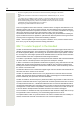
The structure of the VLAN Tag defined in 802.1Q is illustrated in the <Blue>Figure 1.
Figure 1.
Figure 1 Structure of a VLAN Tag.
NOTE: The use of the 802.1Q VLAN tag does not require an implementation of a full-blown VLAN
system since by default all devices belong to the same VLAN and thus can communicate with each
other. This VLAN is often called the native VLAN, and often has a VLAN ID of 0.
DiffServ, DSCP Value
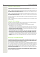
The structure of the use of the ToS Field for both the DSCP (new standard) value and IP Prece-
dence (old standard) is illustrated in the <Blue>Figure 2.
Figure 2.
Figure 2 Diffserv Redefinition of ToS Field.
NOTE: Which version of the standard used depends on the software implementation of the switch
port. An older device receiving a DSCP field set using the 6 bit code may interpret this as a 3-bit
code and drop the last 3 bits, thus efficiently changing the value when the packet is forwarded.
End-to-End QoS
To achieve QoS for a phone call, it is important that QoS is enabled or managed all the way be-
tween the two endpoints. By following a speech packet as it travels along the path between the
endpoints, it is possible to identify all network segments and transitions where QoS needs to be
managed.
Uplink, Handset to AP
The prioritization in the uplink (from handset to AP) is handled by the handset. An internal classi-
fication is done at the low-level MAC software and ensures that voice packets are transmitted prior
to any other data. All voice packets are marked both with an 802.1D user priority (Layer 2) as well
as IP DSCP (Layer 3). By default, the handset marks the DSCP field with the appropriate standard
value for real-time data.
87 654 321 87 6543 21
2
1
Prirority Mark
VLAN Identifier (VID)
= 1 Bit
Octets
002
87 654 321
IP Precedence
ToS
003
DSCP
Unused