
Operating instructions


OM-HY-6E
7
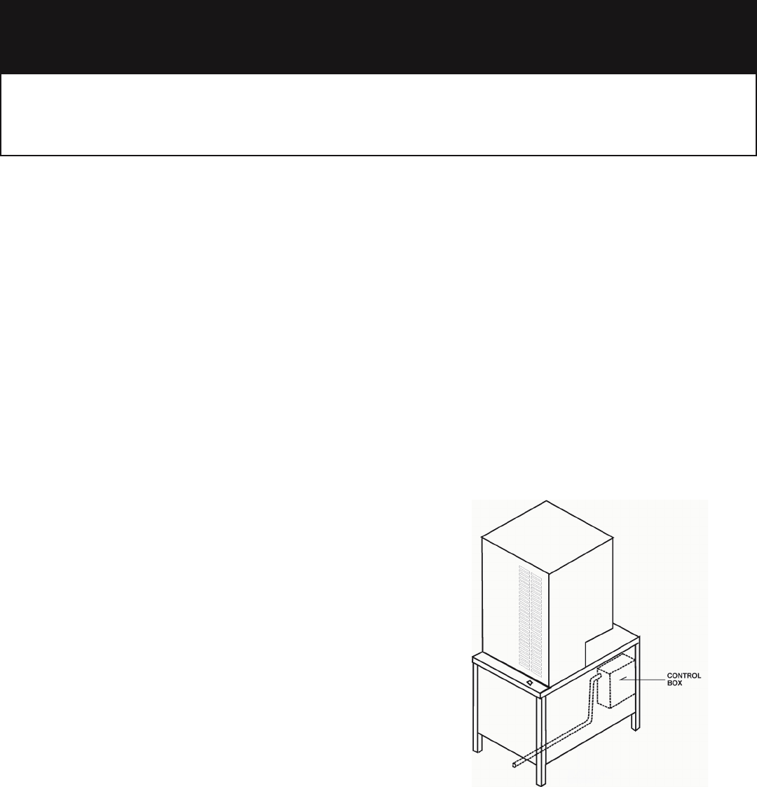
The knockout hole is sized for a one
inch conduit fitting. Pass the wire
up the back through this knockout
hole to the front. Make the
connections from the front.
Installation and Start-Up
WARNING
THE UNIT MUST BE INSTALLED BY PERSONNEL WHO ARE QUALIFIED TO WORK WITH ELECTRICITY AND
PLUMBING. IMPROPER INSTALLATION CAN CAUSE INJURY TO PERSONNEL AND/OR DAMAGE TO THE
EQUIPMENT. THE UNIT MUST BE INSTALLED IN ACCORDANCE WITH APPLICABLE CODES.
CAUTION
DO NOT INSTALL THE UNIT WITH THE RIGHT SIDE VENTS BLOCKED OR WITHIN 12 INCHES OF A HEAT SOURCE
(SUCH AS A BRAISING PAN, DEEP FRYER, CHAR-BROILER, OR KETTLE).
TO AVOID DRAINAGE PROBLEMS, LEVEL THE UNIT FRONT TO BACK.
1. Electrical Supply Connection
A. Access for Connection
Panel Removal
Open the wiring and control panel by removing
screws from the front panel. Lift the panel, and
swing its bottom toward you. Set the panel aside.
B. Supply Voltage
The unit must be operated at the rated nameplate
voltage. A temporary fluctuation of plus or minus 10
percent is acceptable.
C. Phase Selection
Refer to the steamer schematic (at the back of this
manual) for wiring information.
D. Terminal Block
The terminal block for incoming power is located at
the back of the control compartment.
The ground terminal is located in the wiring
compartment next to the terminal block. The unit
must have a separate ground wire for safe
operation. Minimum size for the ground wire is 10
AWG.
E. Supply Wire
To determine the type of wire you need for the power
supply, find the operating voltage and number of
phases on the unit data plate. Refer to the table
provided on the next page or to the label on the
unit’s back for the correct wire size and insulation
temperature rating. The “Electrical Supply
Connection” label inside the unit gives directions for
proper connection of the terminal block jumpers. The
wire specified has to be used, or the unit will not
meet Underwriters Laboratories and National
Electrical Code requirements.
7
om-HY-6e
7