
Specifications


Table Of Contents
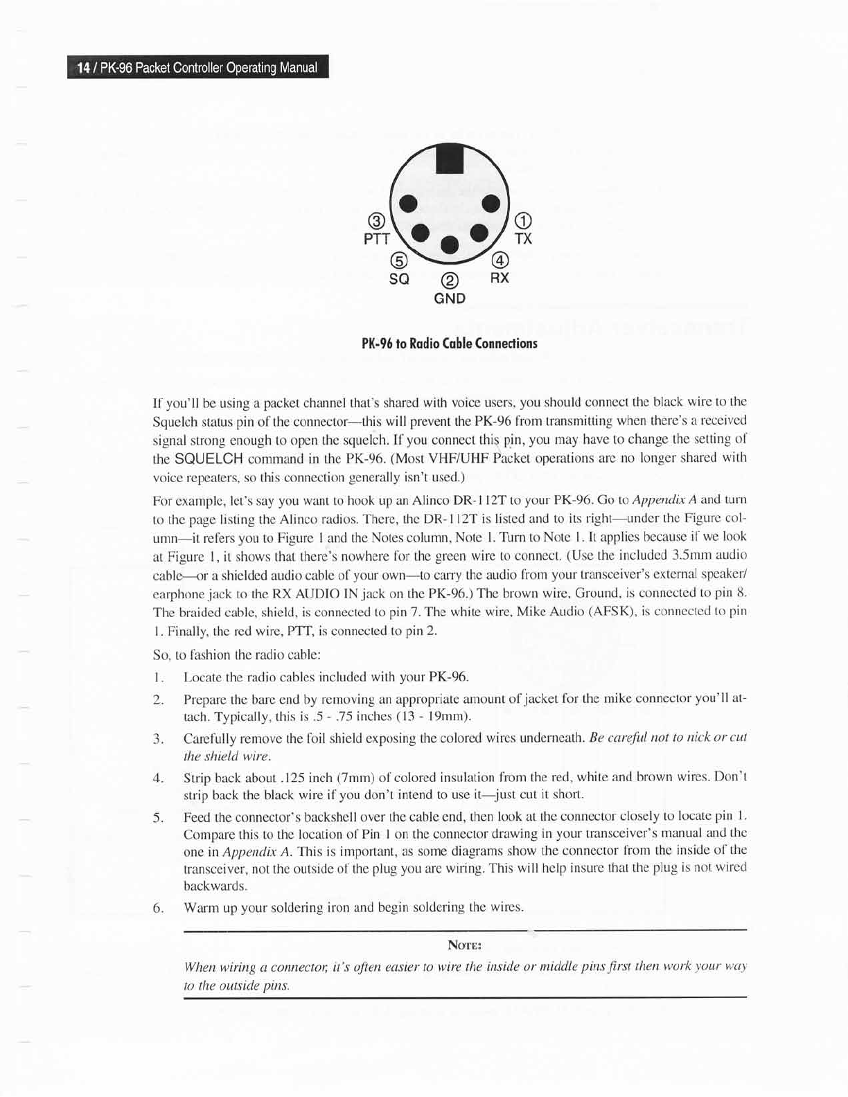
o
TX
@
SQ
@
RX
@
GND
PK-96 lo Rodio Coble
Conneclions
If
you'll
be using a
packet
channel
that's shared with
voice users,
you
should connect
the black
wire to the
Squelch
status
pin
of the connector-this
will
prevent
the
PK-96 from transmitting
when there's a
received
signal strong enough to
open the squelch. If
you
connect
this
pin, you
may have to
change the
setting of
the
SQUELCH command
in the PK-96.
(Most
VHF/UHF
Packet operations are
no longer
shared
with
voice
repeaters, so this connection
generally
isn't used.)
For example, let's say
you want to hook up an
Alinco DR- I l2T to
your PK-96. Go
to Appendx
A and turn
to the
page listing
theAlinco
radios.
Thcre,
the
DR-l l2T
is listed and to
its right-under
the Figurc
col-
umn-it
ref'ers
you
to Figure
I and the Notes column,
Note l.
Turn to Note
l. It applies because
if
we look
at Figure l, it shows
that there's
nowhere lbr the
green
wire to connect.
(Use
the
included 3.5mm
audio
cable----or
a shielded audio cable
ol
your
own-to cany
the audio
lrom
your
transceiver's
external speaker/
earphone
jack
to the
RX AUDIO INjack
on
the
PK-96.)
The brown
wire,
Ground,
is
connectcd
to
pin 8.
The braided cable,
shield, is connected to
pin
7. Thc white
wire, Mike ALrdio
(AFSK),
is connected
to
pin
l. Finally, the red
wire, PTT, is
connected
to
pin
2.
So, to
fashion the radio cable:
l. Locate the
radio cables included
with
your
PK-96.
2. Prepare the bare end by
removing an appropriate
amount of
jacket
for the
mike connector
you'll
at-
tach. Typically, this
is.5
-.75
inches
(13
- l9mm).
3. Carefully
remove the foil shield
exposing the colored
wires underneath.
Be
careful
not
to nick or
cut
the shield wire.
4. Strip back about.l25
inch
(7mm)
of colored
insulation
fiom the red,
white and brown
wires.
Don't
strip back
the black
wire if
you
don't intend to use
it-jttst cut
it short.
5. Feed the connector's
backshell
over the cable end,
then look at
the connector
closely
to locate
pin
l.
Compare this to the
location of
Pin I on the connector
drawing
in
your
transceiver's
manual and
the
one in Appendix
A.This
is important, as some diagrams
show
the connector
fiom the
inside of
the
transceiver,
not the outside of
the
plug you
are
wiring. This
will help insure
that the
ph"rg
is not
wired
backwards"
6. Warm up
your
soldering
iron and begin soldering
the wires.
Ncnr:
When wiring a connectot;
it's often easier
to wire the inside or
middle
pins
first
then
work
your
way
to the outside
pins.
oo
9o9