
Specifications


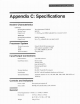


Table Of Contents
bps approximates
a square wave signal which
produces
strong odd harmonics that are necessqry to the
suc-
cessful recovery of
the
data! The
harmonics also need
to be transmitted so that the square-wave
may
be
re-
covered
at
the receiving
end. This is
tricky-if the harmonics are attenuated too much, the signal
at
the re-
ceiver will end
up a sine
wave
(lack
of clean
edges),
yet
if
the
harmonics
are too strong, the transmitted
bandwidth is
wider than it needs to
be and
will
bleed
into
adjacent channels.
At
the other end, we have to deal with long
streams of 1's and 0's which are
low
frequency
in
the audio
world. The transmit injection
point
in
the radio must be able to deal with frequencies approaching DC
(0
Hz)-again, something
that the mic audio input is incapable of! This requirement is
actually
the hardest one
to deal with. In
theory, we need a transmitter
that is
capable
of
moving
off
frequency
and staying there
in-
definitely. To do
this,
we need
to have a directly
coupled transmit
path
inside
the
radio.
Any capacitors in the
transmit
path
will
increase the lowest
passing
frequency allowed to the transmitter, which is undesirable. It is
much easier to
use radios with crystals than
synthesized radios, since synthesized radios have
phase-locked
loops
(PLL's)
that keep the transmitter
on frequency.
Crystal-controlled
radios do not have PLL's that are
trying
to
put
the transmitter back
on
frequency,
and therefore do
not
have this
problem.
Since it is
the synthesizer's
job
to keep the radio on frequency, it is
a
problem
in
regards to transmitting data
that requires
the transmitter to be some distance off frequency for
an extended
period
of time.
The PLL's
loop
consists of a
low-pass
frlter that
provides
f'eedback to
the
phase
lock hardware telling it whether thc out-
put
frequency is
off-frequency or not.
This
process
is fairly slow moving in order to keep the PLL liom
modulating
the signal itself with
quick
changes in its output. What this all means is that the PLL
will
allow
the transmitter to
be off frequency for a short
period
of
time,
and
it
is
fairly
sluggish to adiust
for
the
I're-
quency
enor. This
time constant differs between radios,
making it tough to figure out which radios will work
well with
high-speed data transmissions.
The longer the time constant,
the
longer it will
take
for
the data
to
drop
back to the carrier frequency-the more
'square'
the data will look.
We have no
control of the data sent by the modem
over the air-it could be a continuous stream of I's or 0's,
which would require
the transmitter to stay
off frequency for a
great
length of time. Because of the PLL, this
is
not
going
to happen with a
synthesized radio, so we need some way
of altering the data to
guarantee
that
the data changes
often enough to keep the PLL happy. This is
the
purpose
of the data scrambler/descrambler
circuitry in the modem. The
scrambler multiplies the
outgoing data stream by a
polynomial
and the
descrambler divides
the incoming data stream
by the same
polynomial
to convert the data back to the origi-
nal
code. The scrambler
does not come for
"f1ss"-any
bit errors that are encountered
propagate
through the
polynomial,
aflecting more
bits than the one with the error in it.
As
mentioned above,
receiving
the 9600 bps data requires a wide receiver fiont-end
capable of
passing
the
harmonics which
square
up
the
signal. Narrow filters on the front-end
of the radio will remove too many of
the harmonics, thereby
removing the corners of the square-wave
and
making
it
hard
to recover the data.
The
wide-band
signal required
by the modem is far
too
wide
to
make
it to the speaker of the radio-discriminator
audio required for
9600 bps
data reception.
9600
bps data should be transmitted
on the ur at2.4 kHz
deviation
for maximum
efficiency.
True FSK sig-
nals
require modulation
levels equal to the highest
transmitted frequency
(4.8
kHz in
this
case), but MSK
signals require half
of the modulation level
of
FSK
signals for maximum
efficiency.
It is imperative
that the
level
on the air is
properly
set! We cannot tell
you
to adjust it
'by
ear' based on unsquelched
noise
berng
1007o.
Unsquelched
noise
ranges
from 2 to
5
times
that of
properly
modulated signals, based on the radio
being
used. Not only will
'by
ear' adjustments
cause
problems
in actual operation, but it wili in fact cause
some
customers to operate illegally
by interfering with adjacent
channel users!
It should
be apparent
by now that the
9600 bps
ports
and 1 200 bps
ports
on the
radio
are not
interchangeable
without
additional hardware in
the modem
(pre-emphasis
and
de-emphasis circuits).
Because
of the requirements
to
pass
the harmonics of
the 9600 bps signal,
and
the ability of the radio to
bleed
into adjacent
channels
if
the level
is
too high, the modulation level
of the 9600 bps signal
is
f'ar more
critical to
system
performance
than that of the 1200 bps signal.