Digital Depth Sounder OPERATING GUIDE
Contents Unpacking . . . . . . . . . . . . . . . . . . . . . . . . . . . . . . . 2 Features . . . . . . . . . . . . . . . . . . . . . . . . . . . . . . . . 2 Installing the QT 206. . . . . . . . . . . . . . . . . . . . . . . . . . 3 Transducer Wiring . . . . . . . . . . . . . . . . . . . . . . . . . . . 4 Power Cable Wiring . . . . . . . . . . . . . . . . . . . . . . . . . . 4 Installing The Transducer . . . . . . . . . . . . . . . . . . . . . . . 5 Transom Mount Transducers . . . . . . . . . . . . . . . .
UNPACKING Your QT-206 Depth Sounder box should contain the following items: • Transducer with 3 lugs attached • Power Cable (attached to the gauge) • Mounting Bracket and hardware • This Operating Guide If any items are missing or damaged, please contact your dealer immediately. FEATURES n Depth Readings – The QT-206 is designed to give depth readings from 2.5 feet to a maximum depth of 199 feet. Depth readings are in 1/10 foot increments from 2.
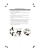
INSTALLING THE QT-206 1. Find a location on your dash panel which will provide clear viewing and access to the LCD window. 2. After finding the right location for the indicator unit, mark a 2-inch hole to be cut out. 3. Check behind the panel for any cables or wiring which could be damaged. Then cut out the 2-inch hole. 4. Test fit the unit in the hole, and make any adjustments with your saw or drill. 5. Extending out of the back of the instrument is a brass shaft.
TRANSDUCER WIRING On the rear of the unit, locate the terminal lugs extending out of the rear of the instrument. These terminals are used to connect the transducer wires. When shipped from the factory, the transducer is wired with 3 female lugs attached. These lugs need to be inserted onto the male terminals located on the rear of the gauge. The BLACK terminal is connected to the BLACK wire. The WHITE terminal may be connected to either the RED, BLUE, or WHITE wire.
1. Connect the main unit to a 12-volt battery using the power cable supplied with your unit. You may extend this cable as necessary, but you must observe proper polarity (i.e., RED is positive and BLACK is negative). 2. Connect the BLACK wire to the negative (-) battery terminal. 3. Connect the RED wire to the positive (+) battery terminal. 4. Make sure the connections are clean and tight so they do not vibrate loose during the boat’s operation.
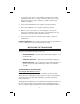
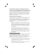
transducer directly behind any strakes, ribs, intakes and outlets for live wells and/or engine cooling water, or any protrusion which may cause turbulence or cavitation. On slower, heavier displacement boats, good results can be achieved further from the keel. FIBERGLASS V-HULL BOATS—TWIN ENGINE (MODERATE TO DEEP-VEE DEADRISE ANGLE) FIBERGLASS V-HULL MODERATE TO LARGE DEADRISE TRANSDUCER IS BELOW STRAIGHT LINE EXTENSION OF HULL. HULL DO NOT INSTALL YOUR TRANSDUCER UNDERNEATH A GASOLINE OVERFLOW.
3. Mark the outline of each slot on the hull. Mark the screw locations 1/8" from the bottom of each slot, and drill four holes 3/4" deep with a 9/64" drill. The slots in the bracket allow 5/8" of vertical adjustment which can be utilized to lower the transducer further into the water to achieve optimal performance. 4. Using the sheet metal screws provided, attach and tighten the bracket to the hull so that the transducer projects 1/8" below the underside of the hull.
have a solvent base. However, some solvent bases will damage encapsulation materials and plastics to varying degrees. If you need anti-fouling protection, use only paints with a mineral spirits base; do not use acetone vinyl-based paints. Glochester (RULE) Durapoxy is a hard, mineral spirits-based paint that has been found to be virtually transparent to acoustic energy. Never apply paint to the transducer by spraying; use a brush or roller.
• Do not install it on a lifting strake since this is the area where air bubbles travel from the bow to the stern, to provide a smooth ride. • On displacement power boats (trawlers), mount the transducer well aft and close to the centerline. • On I/Os, mount the transducer close to the engine(s). • On inboards, always mount the transducer well ahead of the propeller(s), and shafts.
5. Apply a 1/8" thick layer of sealant around the lip of the plastic or bronze housing. A thin layer should also be applied up the sidewalls to a height of 1/4" greater than the hull thickness. This will ensure there is sealant material in the threads to seal them, and hold the housing nut securely in place. 6. From the outside of the hull, push the housing (with sealant applied) into the drilled hole. Apply a twisting motion to the housing to squeeze out excess sealant.
3/4" PIPE THREAD 4" FAIRING BLOCK HULL 1 1/4 " 3" Mounting the Transducer 1. Drill a 1/8" pilot hole in the preferred transducer location. Refer to the previous section to determine the best location for your type of boat. 2. Drill a hole “slightly” larger than the stem of the transducer. Be careful not to make it too large as you will run the risk of water leaking into the hull. 3.
INSIDE-THE-HULL TRANSDUCERS This type of transducer does not require the drilling of a hole as does the Through-the-Hull Transducer. However, since the sound waves transmitted and received by the Inside-the-Hull Transducer must pass through the hull, transducer performance will be reduced. The success of Inside-the-Hull installation is greatly dependent upon the purity of the hull directly below the transducer and the type of hull.
Use one of the following methods to determine if your chosen location is satisfactory: 1. Place the transducer in a plastic bag filled 1/2 to 3/4 full of water. Tie or tape the bag tightly around the transducer cable. Wet the selected location and place the bag against the hull, pressing the transducer face against the hull. If the hull is void free at this point, the depth sounder should now operate. 2. Coat the face of the transducer with silicone grease or petroleum jelly.
UNDERSTANDING SONAR All depth sounders emit ultrasonic sound signals from the transducer into the water located under your boat. These sound signals travel through the water at a rate of approximately 4,800 feet per second (1500 meters per second). The depth sounder transmits a signal and receives a returning echo. The unit calculates the amount of time in microseconds that elapsed while the signal traveled down to the bottom and returned back to the transducer.
SETTING THE SHALLOW WATER ALARM Located just below the LCD window are two keys labeled “DOWN” and “UP” Alarms. These keys are used to set the Shallow Water depth alarm so that it will audibly alert you if you enter water shallower than your preset depth alarm. To set the alarm, press the “DOWN” key. The LCD shows an alarm depth of A03. Pressing the “DOWN” continuously cycles the alarm setting deeper by one foot increments from A03 through A10 (for example: 3, 4, 5, 6, 7, 8, 9, 10).
SHALLOW WATER SENSITIVITY The Shallow Water Sensitivity controls a circuit in the depth sounder that affects the first 10 feet of water. It alters the system’s response time in this area only, and can be used to compensate for installation imperfections. Example: • SHALLOW READINGS: If your instrument occasionally displays random, false shallow readings such as 3.1’, 2.8’, and 4.3’, you may need to adjust this control.
WHEN TO USE LESS SENSITIVITY: SHALLOW READINGS Use less sensitivity when your instrument displays a series of random, shallow readings (3.5’, 2.9’, 4.1’) and the actual depth is greater. How to Perform When looking at the rear of the instrument, this adjustment is made in a clockwise direction. (This control operates much like the volume control on a radio. If you turn it all the way down, you cannot hear the music. Turning it up too far makes the music blare and sound out of tune.
WHEN TO USE MORE SENSITIVITY: DOUBLE ECHOES (READINGS TOO DEEP) Use more sensitivity when your instrument displays depths that are too deep; that is, greater than the actual depth. For example, if you are in 6’ of water and turn this control too far in the less sensitivity direction, you may see “12.0’” appear in the LCD window. This is very dangerous since you will actually be operating the boat in shallower water than what is displayed.
TROUBLESHOOTING GUIDELINE Symptom “0.0" is flashing in the display window. Possible Reasons Unit is not receiving an echo which could be caused by a variety of reasons: Suggested Solutions Correctly adjust the Sensitivity Control so that the numbers in the display window start to appear and are reading the correct depth. Sensitivity Adjustment was turned too much in one direction, actually Try a “known good” squelching out the echo.
Symptom Unit is not reading properly at high speeds, causing high random numbers at high RPM. Possible Reasons There are three basic types of installations: Inside-the-Hull, Through-the-Hull, and Transom Mount. Generally, this situation is attributed to the location and installation of the transducer. A great deal of air is flowing over the face of the transducer and is inhibiting the unit from receiving the correct bottom reading.
One Year Limited Warranty WARRANTOR: UNIDEN AMERICA CORPORATION (“Uniden”) ELEMENTS OF WARRANTY: Uniden warrants, for one year, to the original retail owner, this Uniden Product to be free from defects in materials and craftsmanship with only the limitations or exclusions set out below. WARRANTY DURATION: This warranty to the original user shall terminate and be of no further effect 12 months after the date of original retail sale.
©1995,1996 Uniden America Corporation Printed in the United States of America All rights reserved.