
Installation Instructions


55
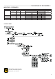
Servicing schedule
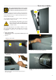
Second phase - Cleaning
• Remove the gaskets and the burners.
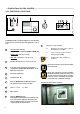
• Performcleaningoftheburnersonlybyblowing,withcom-
pressed air, acting from the “side flame”
• VerifyvisuallythestateofthespotweldingsoftheLproles
and the burner mesh.
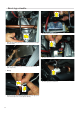
The burner gaskets must be replaced at
every cleaning operation.
• Wash with water the combustion chamber, avoiding to wet
the electrical harness
During this operation it will be necessary to ascertain that
the condensate drain pipe is free, so that the washing water
does not come out from the inspection hole.
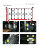
• Blow the combustion chamber with compressed air, trying to
remove all the dirt still fixed to the fins.
• Once the washing of the aluminium sections is finished, make
sure the siphon for the evacuation of the condensate is free:
if necessary clean it
• Ispect the smoke evacuation pipe and the chimney
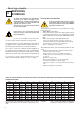
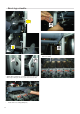
Third phase – Reassembly
When reassembly, proceed in the reverse
order, taking care to tight the fixing screws
of the mixer/fan group to the body, with a
tightening torque of 13 Nm
WARNING
AT EACH MAINTENANCE OPERATION IT IS
COMPULSORY TO REPLACE THE SEALING
GASKETS ON EACH BURNER.
Spare parts code:
00251482 - KIT OF BURNER GASKETS
MODULEX (5 pz.)
95262823 - KIT BURNER MODULEX E8
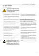
• Beforelightingtheboilermakesurethesiphonhasbeenlled
with water.
• Beforeopening the gas feedingcock,previously unloosed,
make sure it is well tight. To do this open the gas cock and
check with a soap solution.
• Whenasingleburnerisstarted,checkimmediatelyforthe
soundness between its gas valve and the relevant premixing
chamber.
• Performthecombustionanalysischeckitsparameters.
• Makesurethatallthepressuretestnipples,previously
opened, have been closed.
• Afterthecleaningoftheboilerbodyand/ortheburners,re
position the burners in their seats.
• Positionthenewgasketsingraphite
COMPRESSED AIR