
Installation Instructions

12
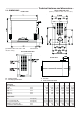
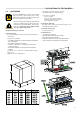
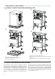
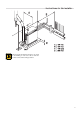
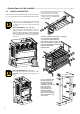
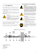
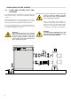
Technical features and dimensions
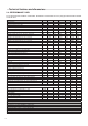
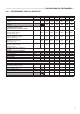
2.4 - PERFORMANCE DATA
Fortheadjustmentdata:NOZZLES-PRESSURE-DIAGRAMS-FLOWRATESrefertotheparagraphADAPTATIONTOOTHER
TYPESOFGAS.
MODULEX EXT100 EXT150 EXT200 EXT250 EXT300 EXT350
Boiler category II
2H3P
II
2H3P
II
2H3P
II
2H3P
II
2H3P
Modulation ratio 1:8,3 1:12,5 1:16,7 1:20,8 1:25 1:29
Rated heat output on P.C.I. Qn kW 100 150 200 250 300 348
Minimum heat output on P.C.I. Qmin kW 12 12 12 12 12 12
Rated useful power (Tr 60 / Tm 80 °C) Pn kW 97,2 146,1 195,2 244,5 294 341,7
Minimum useful power (Tr 60 / Tm 80 °C) Pn min kW 11,7 11,7 11,7 11,7 11,7 11,7
Rated useful power (Tr 30 / Tm 50 °C) Pcond kW 100,1 150 200,4 251,3 302,7 354,6
Minimum useful power (Tr 30 / Tm 50 °C) Pcond min kW 12,8 12,8 12,8 12,8 12,8 12,8
Rated power performance (Tr 60 / Tm 80°C) % 97,2 97,4 97,6 97,8 98,0 98,2
Minimum power performance (Tr 60 / Tm 80°C) % 97,16 97,16 97,16 97,16 97,16 97,16
Rated power performance (Tr 30 / Tm 50°C) % 100,1 100,0 100,2 100,5 100,9 101,9
Minimum power performance (Tr 30 / Tm 50°C) % 106,5 106,5 106,5 106,5 106,5 106,5
Performance at 30% of the load (Tr 30°C) 107,3 107,3 107,3 107,3 107,3 107,3
Combustionefciencyatnominalload % 97,8 97,8 97,8 98,0 98,1 98,3
Combustionefciencywithreducedload % 98,3 98,3 98,3 98,3 98,3 98,3
Casing heat loss with burner operating (Qmin) % 1,2 1,2 1,2 1,2 1,2 1,2
Casing heat loss with burner operating (Qn) % 0,6 0,4 0,2 0,2 0,1 0,1
Netuegastemperaturetf-ta(min)(**) °C 33,4 33,4 33,4 33,4 33,4 33,4
Netuegastemperaturetf-ta(max)(**) °C 44,2 45,1 46,5 47,3 48,2 49,1
Maximum permitted temperature °C 100 100 100 100 100 100
Maximum operating temperature °C 85 85 85 85 85 85
Fluegasmassowrate(min) kg/h 19,6 19,6 19,6 19,6 19,6 19,6
Fluegasmassowrate(max) kg/h 163 245 327 409 490 569
Excess air % 25,5 25,5 25,5 25,5 25,5 25,5
Heat loss at chimney with burner on (min) % 1,7 1,7 1,7 1,7 1,7 1,7
Heat loss at chimney with burner on (max) % 2,2 2,2 2,2 2,2 1,9 1,7
Minimum heating circuit pressure bar 0,5 0,5 0,5 0,5 0,5 0,5
Maximum heating circuit pressure bar 6 6 6 6 6 6
Water content l 10,1 14,2 18,3 22,4 26,5 30,6
MethanegasconsumptionG20(pow.sup.20mbar)atQn m
3
/h 10,6 15,9 21,1 26,4 31,7 36,8
MethanegasconsumptionG20(pow.sup.20mbar)atQmin m
3
/h 1,3 1,3 1,3 1,3 1,3 1,3
GasconsumptionG25(pow.sup.20/25mbar)atQn m
3
/h 12,3 18,4 24,6 36,7 36,9 42,8
GasconsumptionG25(pow.sup.20/25mbar)atQmin m
3
/h 1,5 1,5 1,5 1,5 1,5 1,5
Propanegasconsumption(pow.sup.37/50mbar)atQn kg/h 7,8 11,6 15,5 19,4 23,3 27
Propanegasconsumption(pow.sup.37/50mbar)atQmin kg/h 0,9 0,9 0,9 0,9 0,9 0,9
Chimney base maximum pressure available Pa 100 100 100 100 100 100
Max condensate production kg/h 15,3 23 30,6 38,3 45,9 53,6
Emissions
CO at maximum heat output with 0% of O2 mg/kWh 83 83 83 83 83 83
NOx at maximum heat output with 0% of O2 mg/kWh 77 77 77 77 77 77
NOx Class 5 5 5 5 5 5
Electrical data
Power supply voltage/frequency V/Hz 230 / 50 230 / 50 230 / 50 230 / 50 230 / 50 230 / 50
Fuse on the power supply A (R) 6,3 / 10 6,3 / 10 6,3 / 10 6,3 / 10 6,3 / 10 6,3 / 10
(**) Protection rating IP X5D X5D X5D X5D X5D X5D
Room Temperature = 20°C
(*)Temperaturedetectedwithapplianceoperationowrate80°C/ret.60°C
CO
2
(min/max) See table ‘’NOZZLES - PRESSURE’’
Seasonalspaceheatingenergy2009/125CEE(<=400Kw)ηs-seeErPtable
Stand-byheatloss∆T30°C-Pstb-seeErPtable
Consumption in stand-by - Psb - see ErP table
(**) The protection IP is obtained with cap down