
Daim Ntawv Qhia Tus Neeg Siv
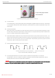
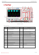
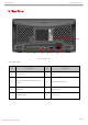
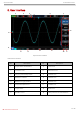
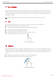
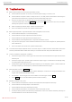
Table Of Contents
- MSO/UPO2000 Series
- Copyright Information
- 1. Safety Requirements
- 2. Introduction of MSO/UPO2000 Series Digital Phosphor Oscilloscope
- 3. Getting Started Guide
- 3.1 General Inspection
- 3.2 Before Use
- (1) Connect to the Power Supply
- (2) Boot Check
- (3) Connect Probe
- (4) Function Check
- (5) Probe Compensation
- When the probe is connected to any input channel for the first time, this step might be adjusted in order to match the probe and the input channel. Probes that are not compensated may lead to measurement errors or mistake. Please follow the following ...
- 4. Front Panel
- 5. Rear Panel
- 6. User Interface
- 7. Touch Screen
- 8. Operation Menu
- 9. Remote Control
- 10. Troubleshooting
- 11. Appendix Contact Us

Quick Start Guide MSO/UPO2000 Series
15 / 18
Instruments.uni-trend.com
Open “trigger area” menu.
Hints: Press “drawing rectangle” icon to switch drawing rectangle and operating waveform mode. Press
“drawing rectangle” icon, if icon displays , which presents the drawing rectangle mode is opened; press
“drawing rectangle” icon, if icon displays , which presents the operating waveform mode is opened.
Operating waveform mode of the oscilloscope is enabled by default.
7.5 Touch Shortcut Operating
Separate two fingers and meanwhile slide two fingers to one direction, this gesture can quickly turn on/off
time measurement and voltage measurement cursor.
a. Time measurement cursor
Slide down in vertical to directly turn on time measurement cursor as shown in Figure 11 (a);
Slide up in vertical to directly turn off time measurement cursor;
b. Voltage measurement cursor
Slide right in horizontal to directly turn on voltage measurement cursor as shown in Figure 11 (b);
Slide left in horizontal to directly turn off voltage measurement cursor;
Note: Turn on/off cursor requires that slide distance should be >3div.
(a) (b)
Figure 11