
User Manual
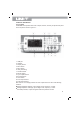
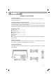

b)Rear Panel
The rear panel is shown in figure 2-2:
1.External analog modulation input connector
2.External digital modulation/ frequency meter connector
3.LAN port
4.USB port
5.External 10MHz input connector
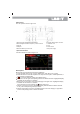
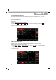
c)Function Interface
Function interface is shown in figure 2-3:
Description:
CH1/CH2: the selected channel will be highlighted.
1) Limit indicates output range is at limit. White color: valid; Grey color: invalid.
2) 50Ω indicates the matched impedance of output terminal (1Ω to 10KΩ adjustable, or
high resistance; default:50Ω)
3) : sine wave. Different modes have different menu.
Bezel menu on the right: corresponding buttons for different function. Highlighted display
indicates that the function is selected.
Bezel menu on the bottom: sub menu belonging to the right menu. Highlighted display
indicates that the function is selected.
If the submenu has over 6 labels, use button to flip over.
1) Labels on the right of screen: Highlighted display indicates that the label is selected.
If not, press corresponding soft key to select.
2) Labels at the bottom of screen: Sub label belongs to the next category of Type label.
Press corresponding button to select sub labels.
6. Internal 10MHz output connector
7. Ventilation vent
8. Fuse
9. Power switch
10.AC power supply
7