
User Manual
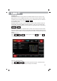
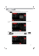
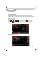
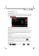
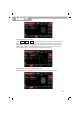
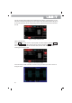
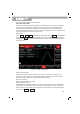
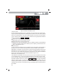

Figure 4- 1 Select carrier waveform
Set carrier frequency
See Carrier Frequency Wave Setting
Select modulation source
UTG2000B function/arbitrary waveform generator can select internal or external modulation
source. After you use PSK function, you can see that modulation source is internal by default.
You can change it with multi-functional knob on the interface for using PSK function or by
pressing Param → Source
1)Internal source
In case of internal modulation source, internal modulation wave is sine wave. The phase
relation between oscillation start and stop can be designated by setting OSK rate.
2)External source
In case of external modulation source, rate will be hidden in parameter list, when an external
waveform will be used to modulate carrier waveform. OSK output phase is determined by
logic level on external digital modulation interface (FSK Trig connector). For example, when
external input logic is low, carrier phase is output; when external input logic is high,
modulation phase is output.
Set vibrate time
Press the soft key and enter the period value. Range: 8ns~200ns, default is 1ms.
Set OSK rate
The frequency between carrier phase and modulation phase can be set in case of internal
modulation source. After you use OSK function, you can set QPSK rate, which is in the
range of 2mHz~1MHz and 100Hz by default. You can change it with multi-functional knob
and direction key on the interface for using PSK function or by pressing Rate.
Comprehensive example
First make the instrument run in OSK mode, and then set an internal sine wave of 2kHz
and 2Vpp as carrier signal. Set rate to be 100Hz and oscillation period to be 1μs. The
specific steps are as follows:
1)OSK function
Press Mod → Type → OSK successively (press soft key Type to select if Type is not
highlighted) to use OSK function.
55