UTG2000B Series Function Generator User Manual
Preface Dear Users: Hello! Thank you for choosing this brand new Uni-Trend device. In order to use this instrument safely and correctly, please read this manual thoroughly, especially the Safety Notes part. After reading this manual, it is recommended to keep the manual at an easily accessible place, preferably close to the device, for future reference. Copyright Information UNI-T is Uni-Trend Technology (China) Limited. All rights reserved.
Table of Contents Preface--------------------------------------------------------------------------------------------------------- 1 Copyright Information--------------------------------------------------------------------------------------- 1 Chapter 1 Safety Information----------------------------------------------------------------------------- 4 1.1 Safety Terms and Symbols------------------------------------------------------------------------ 4 1.
j) Sum Modulation(SUM)----------------------------------------------------------------------- 58 k) Double side band amplitude Modulation (DSBAM)------------------------------------ 62 l) Quadrature Amplitude Modulation(QAM)------------------------------------------------ 66 m) Pulse Width Modulation (PWM)------------------------------------------------------------ 70 4.
Chapter 1 Safety Information 1.1 Safety Terms and Symbols The following terms may appear in this manual: Warning: The conditions and behaviors may endanger life. Note: The conditions and behaviors may cause damage to the product and other properties. The following terms may appear on the product: Danger: This operation may cause immediate damage to the operator. Warning: This operation may cause potential damage to the operator.
Please check the accessories for any mechanical damage before usage. Only use accessories that came with this product. Please do not put metal objects into the input and output terminals of this product. Do not operate the product if you suspect it is faulty, and please contact UNI-T authorized service personnel for inspection. Please do not operate the product when the instrument box opens. Please do not operate the product in humid conditions. Please keep the product surface clean and dry.
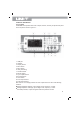
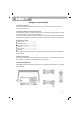
2.2Panels and Buttons a) Front Panel UTG2000B series provides users with a simple, intuitive, and easy to operate front panel. The front panel is shown in figure 2-1: 1. USB port 2. ON/OFF 3. Display Screen 4. Menu button 5. Menu button 6. Utility and setting 7. Number buttons 8. Manual trigger 9. Sync output terminal 10.Functional knob 11.Arrow button 12.CH1 output terminal 13.
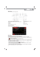
b)Rear Panel The rear panel is shown in figure 2-2: 1.External analog modulation input connector 2.External digital modulation/ frequency meter connector 3.LAN port 4.USB port 5.External 10MHz input connector 6. Internal 10MHz output connector 7. Ventilation vent 8. Fuse 9. Power switch 10.AC power supply c)Function Interface Function interface is shown in figure 2-3: Description: CH1/CH2: the selected channel will be highlighted. 1) Limit indicates output range is at limit.
Chapter 3 Quick Start 3.1General Inspection It is recommended to follow the steps below to check the instrument before using this device for the first time. a) Check for Damages Caused by Transport If the packaging carton or the foam plastic cushions are severely damaged, please contact the UNI-T distributor of this product immediately.
3.3 Basic Waveform Output This chapter introduces how to output different waveforms. Default waveform: sine wave with 1 kHz and 100mVpp. a) Set output frequency Default waveform: A sine wave of 1 kHz frequency and 100mV amplitude (with 50Ω termination). Steps for setting the frequency to 2.5MHz: 1) Press Menu → Wave → Param → Freq in turn to set the frequency. Pressing Freq to edit frequency or period. 2) Press the number keyboard to input 2.5.
c) Set DC offset voltage Default waveform: sine wave with 0V DC offset voltage (with 50Ω termination).Steps for setting DC offset voltage to -150mV: 1. Press Menu → Wave → Param → Offset 2. Use number keys to input the required number of -150. 3. Select corresponding unit mV. Note: if the current DC offset value is valid, use this value. Press offset again, the parameters become high level (MAX) and low level (MIN). d)Set square wave Default duty ratio: 50% limited by minimum pulse width 6.5ns.
e)Set pulse wave Example: period=2ms, amplitude=1.5Vpp, offset=0V, duty=25%, rising time=200us and falling time=200us: 1. Press Menu → Wave → Type → Pulse → Param , and then press Freq to switch to Period. Enter required number value and select the unit. When entering duty ratio value, there is a label at the bottom of display, and select 25%. 2. Press Param to enter sub menu to set falling edge time, then press Fall to enter required number and select unit.
g)Set ramp wave Default symmetry degree of ramp wave: 100%. Steps for setting a ramp wave with 10 kHz frequency, 2V amplitude, 0V DC offset and 50% duty ratio: 1.Press Menu → Wave → Type → Ramp → Param 2.Select the parameter to enter edit mode, then input required numbers and select unit. Note: When enter symmetry degree value, press 50% label at the bottom of the display. h)Set noise wave Default noise: Gauss noise with amplitude 100mVpp and DC offset 0mV.
I)Set harmonic Wave Default frequency:1kHz, amplitude 100mVpp, DC offset 0mV, phase position 0°,harmonic wave type is odd order, total is 2 times, current is 2 times. Amplitude 100mV, phase position 0°Steps for setting the harmonic wave type is all, wave time is 2 times, amplitude is 4Vpp, phase position is 0°: Press Menu → Wave → Type → Harmonic → Param in turn to enter parameter editing mode. After setting, enter number and unit.
Change Exp Start and Exp End to determine X value, press Exp Start and input 1.4rad (or °): Press Expression to enter the edit interface, press Next to cycle switch oeperational character or expression. E.
1.Press Menu → wave → Type → Exp → Param Input number and select the unit. 3.4 Frequency Measurement This instrument can measure frequency and duty ratio of TTL compatible signals, with frequency range of 100 MHz to 200MHz. The frequency meter takes signal through the external digital modulation interface (FSK Trig/CNT connector). Press Utility → Counter to collect Frequency, Period, and Duty ratio values.
Chapter 4 Advanced Applications 4.1 Generate Modulation Waveform a)Amplitude Modulation (AM) In AM modulation, modulated waveform is usually composed of carrier wave and modulation wave. The modulation of CH1 and CH2 is independent, you can set up the same or different mode for them. Press Menu → Mod → Type → AM to enable the AM function. Then the modulated waveform will be displayed with modulation waveform and carrier wave Select Carrier Waveform Press Carrier to select a carrier waveform.
Frequency UTG2122B Carrier Wave UTG2082B UTG2062B Minimum Value Maximum Value Minimum Value Maximum Value Minimum Value Maximum Value Sine wave 1µHz 120MHz 1µHz 80MHz 1µHz 60MHz Square wave 1µHz 30MHz 1µHz 30MHz 1µHz 30MHz Ramp wave 1µHz 5MHz 1µHz 4MHz 1µHz 3MHz Impulse wave 1µHz 30MHz 1µHz 25MHz 1µHz 20MHz Arbitrary wave 1µHz 25MHz 1µHz 20MHz 1µHz 15MHz Modulation Source Selection Both internal and external modulation source are compatible.
2) External Source When modulation source is external, parameter list will hide the modulation wave option and modulation frequency option, and carrier waveform will be modulated by an external waveform. AM modulation depth is controlled by ±5V signal level of external modulation input terminal Modulation In connector).
Set Modulation Signal Parameter After enabling the AM function, press Param soft key and the interface will appear as following: Press corresponding soft key, then enter required numerical value, and select the unit.
Set Carrier Wave Signal Parameter Press Carrier → Type → Square in turn to select square wave as carrier wave signal. Press Param soft key again, and the interface will pop up as following: Press corresponding soft key, then enter required numerical value, and select the unit.
Set Modulation Depth After setting carrier wave parameter, press Return soft key to back to the following interface for setting modulation depth. Press Param → depth soft key again, then enter number 80 and press % soft key with number keyboard for setting modulation depth. Enable Channel Output Press CH1 button start channel 1 output quickly. Or enable output by pressing Utility and then CH1 Setting .
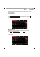
The shape of AM modulation waveform checked through oscilloscope is shown as following: b) Frequency Modulation (FM) In frequency modulation, modulated waveform is usually composed of carrier wave and modulation wave. Carrier wave frequency will change as the amplitude of modulation wave changes. Press Menu → Mod → Type → FM in turn to start the FM function. The device will output modulated waveform according to the setting of modulation wave and carrier wave.
Carrier Wave Waveform FM wave waveform: sine wave, square wave, ramp wave, or arbitrary wave(exp. DC). Default is sine wave. After select FM modulation, press param If you need to set up the carrier wave frequency,see Carrier Wave Frequency Setting Modulation Source Selection This device can select internal modulation source or external modulation source. After enabling FM function, the default of modulation source is internal.
2)External Source When modulation source is external, carrier waveform will be modulated by an external waveform. FM frequency deviation is controlled by ±5V signal level of external modulation input terminal(Modulation In Connector) on front panel. In positive signal level, FM output frequency is more than carrier wave frequency, while in negative signal level, FM output frequency is less than carrier wave frequency. Low external signal level has small deviation.
Set Modulation Signal Parameter Press Param soft key. Then the interface will show as following: Press corresponding soft key, then enter required numerical value, and select the unit.
Set Carrier Wave Signal Parameter Press Carrier → Type → Sine in turn to select sine wave as carrier wave signal. Press Param soft key, and the interface will pop up as following: Press corresponding soft key first, then enter required numerical value, and select the unit.
Set Frequency Deviation After setting carrier wave parameter, press Return soft key to back to the following interface for setting frequency deviation. Press Param → FreDev soft key, then enter number 5 and press kHz soft key with number keyboard for setting frequency deviation. Press CH1 button start channel 1 output quickly. Or enable output by pressing Utility and then CH1 Setting .
The shape of FM modulation waveform checked through oscilloscope is shown as following: c) Phase Modulation (PM) In phase modulation, modulated waveform is usually composed of carrier wave and modulation wave. The modulation of CH1 and CH2 is independent, you can set up the same or different mode for them. Press Menu → Mod → Type → PM in turn to start the PM function. The device will output modulated waveform with modulation waveform and carrier wave set currently.
Carrier Wave Waveform Selection PM carrier waveform can be: Sine wave, square wave, ramp wave or arbitrary wave (except DC), and the default is sine wave. Press Carrier soft key to select carrier waveform. Carrier Wave Frequency Setting If you need to set up the carrier wave frequency,see Carrier Wave Frequency Setting Modulation Source Selection This device can select internal modulation source or external modulation source. After enabling PM function, the default of modulation source is internal.
2) External Source When modulation source is external, carrier waveform will be modulated by an external waveform. PM phase deviation is controlled by ±5V signal level of external modulation input terminal on rear panel. For example, if phase deviation value in parameter list has been set to 180˚, +5V of external modulation signal is equivalent to 180˚ phase shift. Lower external signal produce smaller deviation.
Set Modulation Signal Parameter Press Param soft key and the interface will show as following: Press corresponding soft key first, then enter required numerical value, and select the unit. Set Carrier Wave Signal Parameter Press Carrier → Type → Sine in turn to select sine wave as carrier wave signal.
Press Param soft key, and the interface will pop up as following: Press corresponding soft key, then enter required numerical value, and select the unit. Set Phase Deviation Press Return soft key to back to the following interface for setting phase modulation.
Press Param → PhaseDev soft key, then enter number 200 and press ˚ soft key with number keyboard for setting phase deviation. Enable Channel Output Press CH1 button start channel 1 output quickly. Or enable output by pressing Utility and then CH1 Setting . After channel output is opened, backlight of CH1 button is on, and on the right side of channel information label, the font “OFF” changes to “PM”, meaning open channel output.
d)Amplitude Shift Keying (ASK) ASK shows digital signal “0” and “1” by changing amplitude of carrier wave signal. Carrier wave signal with different amplitude will be output on the basis of different logic of modulation signal. ASK Modulation Selection Press Menu → Mod → Type → ASK in turn to start the ASK function, the device will output modulated waveform with ASK rate and carrier wave set currently.
Carrier Wave Frequency Setting See Carrier Wave Frequency Setting Modulation Source Selection The device can select internal modulation source or external modulation source. After enabling ASK function, the default of modulation source is internal. If need to change, press Param → Source → External in turn. 1)Internal Source When modulation source is internal, internal modulation wave is a square wave of 50% duty ratio (not adjustable).
Enable Amplitude Shift Keying (ASK) Function Press Menu → Mod → Type → ASK in turn to start the ASK function.
Press corresponding soft key, then enter required numerical value, and select the unit. Set ASK Rate After setting carrier wave parameter, press Return soft key to go back to the following interface for setting phase modulation. Press Param → Rate soft key again, then enter number 300 and press Hz soft key with number keyboard for setting ASK rate.
Enable Channel Output Press CH1 button start channel 1 output quickly. Or enable output by pressing Utility and then CH1 Setting. After channel output is opened, backlight of CH1 button is on, and on the right side of channel information label, the font “OFF” changes to “ASK”, meaning open channel output.
Carrier Wave Waveform Selection Press Carrier soft key to enter carrier waveform selection interface. FSK carrier waveform can be: sine wave, square wave, ramp wave or arbitrary wave (except DC), and the default is sine wave. Carrier Wave Frequency Setting See Carrier Wave Frequency Setting Modulation Source Selection The device can select internal modulation source or external modulation source. After enabling FSK function, the default of modulation source is internal.
Hop Frequency Setting After enabling FSK function, the default of hop frequency is 2MHz. If need to change, press Param → HopFreq in turn. Settable range of hop frequency is determined by carrier wave waveform. See Carrier Wave Frequency Setting FSK Rate Setting When modulation source is internal, the moving frequency between carrier wave frequency and hop frequency can be set. After enabling FSK function, FSK rate can be set and the settable range is 2mHz to 1MHz, the default rate is 100Hz.
Press Param soft key again, and the interface will pop up as following: Press corresponding soft key first, then enter required numerical value, and select the unit. Set Hop Frequency and FSK Rate Press Return soft key to go back to the following interface.
Press Param soft key again, and the interface will pop up as following: Press corresponding soft key first, then enter required numerical value, and select the unit. Enable Channel Output Press CH1 button start channel 1 output quickly. Or enable output by pressing Utility and then CH1 Setting . After channel output is opened, backlight of CH1 button is on, and on the right side of channel information label, the font “OFF” changes to “FSK”, meaning open channel output.
The shape of FSK modulation waveform checked through oscilloscope is shown as following: f) Phase Shift Keying (PSK) In phase shift keying, DDS function generator can be configured to move between two preset phase (carrier wave phase and modulation phase). Output carrier wave signal phase or hop signal phase on the basis of the logic of modulation signal. PSK Modulation Selection Press Menu → Mod → Type → PSK in turn to start the PSK function.
Carrier Wave Waveform Selection PSK carrier waveform can be: Sine wave, square, ramp wave or arbitrary wave (except DC), and the default is sine wave. Press Carrier soft key to enter carrier waveform selection interface. Carrier Wave Frequency Setting See Carrier Wave Frequency Setting Modulation Source Selection UTG2000B function/arbitrary waveform generator can select internal modulation source or external modulation source. After enabling PSK function, the default of modulation source is internal.
PSK Rate Setting When modulation source is internal, the moving frequency between carrier wave phase and modulation phase can be set. After enabling PSK function, PSK rate can be set and the settable range is 2mHz to 1MHz, the default rate is 100Hz. If need to change, press Param → Rate in turn. Modulation Phase Setting Modulation phase indicates the change between the phases of PSK modulated waveform and the phase of carrier wave phase.
Press Param soft key, and the interface will pop up as following: Press corresponding soft key, then enter required numerical value, and select the unit.
Press Param soft key, and the interface will pop up as following: Press corresponding soft key, then enter required numerical value, and select the unit. Enable Channel Output Press CH1 button start channel 1 output quickly. Or enable output by pressing Utility and then CH1 Setting . After channel output is opened, backlight of CH1 button is on, and on the right side of channel information label, the font “OFF” changes to “PSK”, meaning open channel output.
The shape of PSK modulation waveform checked through oscilloscope is shown as following: g) Binary Phase Shift Keying (BPSK) The function/arbitrary waveform generator can move between two preset phases (carrier phase and modulation phase) in binary phase shift keying, expressing 0 and 1. Phase of carrier signal or modulation signal is output according to logic of modulation signal. The modulation mode of the two channels is mutually independent.
Select carrier waveform BPSK carrier waveform can be sine wave, square wave, ramp wave or arbitrary wave (except DC), and is sine wave by default. After PSK modulation is selected, press Carrier Parameter to select carrier waveform. Set carrier frequency See Carrier Frequency Wave Setting Select modulation source UTG2000B function/arbitrary waveform generator can select internal or external modulation source. After you enable BPSK function, you can see that modulation source is PN7 by default.
Set BPSK rate The frequency between carrier phase and modulation phase can be set. After you use BPSK function, you can set BPSK rate, which is in the range of 2mHz~1MHz and 100Hz by default. You can change it with multi-functional knob and direction key on the interface for using PSK function or by pressing Param → Rate . Set modulation phase Modulation phase is change in phase of waveform subject to PSK modulation relative to carrier phase. The range of BPSK modulation phase is 0˚~360˚.
You can press Param to setup the parameters. If you need to set up the parameter, input the value and then select the unit.
Set BPSK rate, modulation phase and PN code Press Return to return to the interface below after setting carrier parameters: To set some parameter, press corresponding soft key, input the required value and select the unit. Enable channel output Press CH1 button start channel 1 output quickly. Or enable output by pressing Utility and then CH1 Setting .
Check the shape of BPSK modulation waveform through oscilloscope, which is shown in the figure below: h) Quadrature Phase Shift Keying(QPSK) The function/arbitrary waveform generator can move between four preset phases (carrier phase and 3 modulation phases). Phase of carrier signal or modulation signal is output according to logic of modulation signal. The modulation mode of the two channels is mutually independent. You can configure same or different modulation mode for channel 1 and 2.
Select carrier waveform QPSK carrier waveform can be sine wave, square wave, saw tooth wave or arbitrary wave (except DC), and is sine wave by default. After QPSK modulation is selected, press Carrier to select carrier waveform. i)Oscillation Keying(OSK) The function/arbitrary waveform generator can output a sinusoidal signal of intermittent oscillation in OSK.
Figure 4- 1 Select carrier waveform Set carrier frequency See Carrier Frequency Wave Setting Select modulation source UTG2000B function/arbitrary waveform generator can select internal or external modulation source. After you use PSK function, you can see that modulation source is internal by default.
2)Set carrier signal parameters Press Carrier → Type → Sine to select carrier signal as sine wave. The default carrier signal is sine wave, so it is unnecessary to change in this example. You can set with multi-functional knob and direction key. You can also press corresponding soft keys of function again, when the interface below will pop up. To set some parameter, press corresponding soft key, input the required value and select the unit.
You can set with multi-functional knob and direction key directly on this interface. You can also press corresponding soft keys of function again, when the interface below will pop up. To set some parameter, press corresponding soft key, input the required value and select the unit. Figure 4- 2 Set modulation rate 4)Use channel output Press CH1 button start channel 1 output quickly. Or enable output by pressing Utility and then CH1 Setting .
Figure 4- 4 OSK waveform with oscilloscope j)Sum Modulation(SUM) In SUM, the modulated waveform generally is composed of carrier wave and modulation wave. The output waveform is obtained by the sum of product of carrier amplitude and modulation factor and product of amplitude of modulation wave and modulation factor. The modulation mode of the two channels is mutually independent. You can configure same or different modulation mode for channel 1 and 2.
Figure 4- 6 Select modulation source 1)Internal source In case of internal modulation source, modulation wave can be sine wave, square wave, rising ramp wave, falling ramp wave, arbitrary wave and noise, and is sine wave by default. After you use SUM function, you can see that modulation wave is sine wave by default.
Set modulation depth Modulation depth is degree of amplitude change, expressed in percentage. The range of SUM depth is 0%~100%, 100% by default. When modulation depth is 0%, carrier wave is output. When modulation depth is 100%, modulation wave is output. You can change it with multi-functional knob and direction key on interface for using amplitude modulation function or by pressing Depth .
Figure 4- 8 Set modulation parameters 3)Set FSK rate and modulation phase After setting up, press Return to turn to the interface below: 4)Use channel output Press CH1 button start channel 1 output quickly. Or enable output by pressing Utility and then CH1 Setting . After channel output is opened, backlight of CH1 button is on, and on the right side of channel information label, the font “OFF” changes to “SUM”, meaning open channel output.
k)Double side band amplitude Modulation (DSBAM) Select DSBAM Press Menu → Mod → Type → DSBAM successively to use DSBAM function (if Type is not highlighted, press soft key Type to select). After DSBAM function is used, UTG2000B function/arbitrary waveform generator will output modulated waveform with the current modulation waveform and carrier wave. Select carrier waveform DSBAM carrier waveform can be sine wave, square wave, ramp wave or arbitrary wave (except DC), and is sine wave by default.
Set carrier frequency See Carrier wave frequency setting Select modulation source UTG2000B function/arbitrary waveform generator can select internal or external modulation source. After you use DSBAM function, you can see that modulation source is internal by default.
Set frequency of modulation wave When modulation source is internal, frequency of modulation wave can be modulated. After enabling DSBAM function, default of modulation wave frequency is 100Hz. Press Param → ModFreq to change. Modulation frequency range: 2mHz~1MHz. When modulation source is external, parameter list will hide the modulation wave option and modulation frequency option, and carrier waveform will be modulated by an external waveform.
You can use the multifunctional knob and soft keys to set the parameters. After you press Param , the following interface will be displayed: Input the number and select the unit.
4) Use channel output 5) Press CH1 button start channel 1 output quickly. Or enable output by pressing Utility and then CH1 Setting . After channel output is opened, backlight of CH1 button is on, and on the right side of channel information label, the font “OFF” changes to “DSBAM”, meaning open channel output.
Select QAM Press Menu → Mod → Type → QAM successively to use QAM function (if Type is not highlighted, press soft key Type to select). After QAM function is used, UTG2000B function/arbitrary waveform generator will output modulated waveform with the current carrier phase and modulation phase. Figure 4- 12 Select QAM function Select carrier waveform QAM carrier waveform is sine wave.
After you use QAM function, you can set QAM rate, which is in the range of 2mHz~1MHz and 100Hz by default. You can change it with multi-functional knob and direction key on the interface for using ASK function or by pressing Param → Rate Comprehensive example First make the instrument run in QAM mode, and then set an internal sine wave of 2kHz and 2Vpp as carrier signal. Set rate to be 100Hz and modulation mode to be 64QAM, default source is PN7.
To set some parameter, press corresponding soft key, input the required value and select the unit. Enable channel output Press CH1 button start channel 1 output quickly. Or enable output by pressing Utility and then CH1 Setting . After channel output is opened, backlight of CH1 button is on, and on the right side of channel information label, the font “OFF” changes to “QAM”, meaning open channel output.
m) Pulse Width Modulation (PWM) In PWM, modulated waveform generally is composed of carrier wave and modulation wave. The pulse width of carrier wave will vary with the amplitude of modulation wave. The modulation mode of the two channels is mutually independent. You can configure same or different modulation mode for channel 1 and 2.
Figure 4- 21 Set carrier waveform Set carrier frequency See Carrier Frequency Wave Setting The frequency range of pulse wave is 1μH~30MHz. Default frequency is 1kHz. To set carrier frequency, please use multi-functional knob and direction key in the interface or press soft function key Param → Freq and input the required value and select the unit. Set carrier duty ratio The range of duty ratio of pulse wave is 0.01%~99.99%. Default duty ratio is 50%.
2)External source In case of external modulation source, modulation wave and frequency will be hidden in parameter list, when an external waveform will be used to modulate carrier waveform. Duty ratio deviation of PWM is controlled by ±5V signal level on external analog modulation input terminal (Modulation In connector) of back panel. For example, if duty ratio deviation in parameter list is set to be 15%, duty ratio of carrier signal (pulse wave) increases by 15% when external modulation signal is +5V.
2)Set modulation signal parameters Set with multi-functional knob and direction key after using PWM function. You can also press corresponding soft keys of function on the above interface for using PWM function, when the interface below will pop up. To set some parameter, press corresponding soft key, input the required value and select the unit.
You can set with multi-functional knob and direction key. You can also press corresponding soft keys of function again, when the interface below will pop up. To set some parameter, press corresponding soft key, input the required value and select the unit. Figure 4- 26 Set rising edge 4)Set duty ratio deviation Press Return to return to the interface below to set frequency deviation after setting carrier parameters.
5)Enable channel output Press CH1 button start channel 1 output quickly. Or enable output by pressing Utility and then CH1 Setting . After channel output is opened, backlight of CH1 button is on, and on the right side of channel information label, the font “OFF” changes to “PWM”, meaning open channel output.
4.2 Output Frequency Sweep Waveform When selecting frequency sweep mode, the output frequency of function/arbitrary waveform generator changes in a linear or logarithmic way from starting frequency to stop frequency in designated frequency sweep time. Trigger source can be internal, external or manual; it can generate frequency sweep output for sine wave, square wave, ramp wave and arbitrary wave (except DC). The modulation mode of the two channels is mutually independent.
b)Set Starting and Stop Frequency Starting frequency and stop frequency are upper limit and lower limit of frequency sweep. Function/ arbitrary waveform generator always sweeps from starting frequency to stop frequency and then returns to starting frequency. To set starting or stop frequency, please press Param → StartFreq or StopFreq , input number through numeric keyboard and press corresponding soft key of unit to finish setting.
c)Frequency Sweep Mode For linear frequency sweep, waveform generator changes output frequency in a linear way during frequency sweep; for logarithmic frequency sweep, waveform generator changes output frequency in a logarithmic way. Linear frequency sweep mode is default. To change it, please press soft key Type → Log on the interface for starting frequency sweep mode (please press Return first to enter the interface for selecting frequency sweep waveform).
e)Select Trigger Source The signal generator generates frequency sweep output upon receiving a trigger signal and then waits for the next trigger signal. The trigger source of frequency sweep can be internal, external or manual.
3) In case of manual trigger, backlight of Trigger on front panel flashes. Frequency sweep is output upon pressing Trigger . f) Trigger Output In case of internal or manual trigger source, the trigger signal (square wave) can be output through external digital modulation interface (FSK Trig connector), compatible with TTL level. The default trigger output is “OFF”.
Select frequency sweep waveform After linear frequency sweep function is used, press Carrier → Type → Square to select frequency sweep waveform, when the interface below will pop up: Figure 4- 40 Select frequency sweep waveform You can set amplitude with multi-functional knob and direction key. You can also press corresponding soft function keys again, when the interface below will pop up. To set some parameter, press corresponding soft key, input the required value and select the unit.
3)Set starting/stop frequency, frequency sweep time, trigger source and edge Press Return to return to the interface below after selecting frequency sweep waveform and relevant parameters: Figure 4-42 Set frequency sweep parameters You can set with multi-functional knob and direction key. You can also press corresponding soft function keys again, when the interface below will pop up. To set some parameter, press Param , input the required value and select the unit.
4)Enable channel output Press CH1 button start channel 1 output quickly. Or enable output by pressing Utility and then CH1 Setting . After channel output is opened, backlight of CH1 button is on, and on the right side of channel information label, the font “OFF” changes to “Line”, meaning open channel output. Check the shape of frequency sweep waveform through oscilloscope, which is shown in the figure below: Figure 4- 45 Observe frequency sweep waveform with oscilloscope 4.
a)Select Burst Start Burst function Press Menu → Burst to start function of pulse. After pulse train function is used, UTG2000B function/arbitrary waveform generator will output pulse train with the current setting. Figure 4-46 Select BURST function Select waveform N cycle mode supports sine wave, square wave, ramp wave, pulse wave and arbitrary wave (except DC). Gating mode supports sine wave, square wave, ramp wave, pulse wave, arbitrary wave (except DC) and noise.
3)Set waveform frequency In N cycle and gating modes, waveform frequency defines signal frequency during period of pulse train. In N cycle mode, the pulse train will be output with designated cycle index and waveform frequency. In gating mode, when trigger signal is at high level, pulse train is output with waveform frequency. Note: waveform frequency is different with period of pulse train that designates interval between pulse trains (only for N cycle mode). The default frequency of waveform is 1kHz.
Figure 4-48 Select N cycle mode Gating mode Press soft function keys Type → Gated successively on the interface to enter gating mode. In mode of gating pulse train, trigger source, trigger output, trigger edge, burst period (period of pulse train) and recurring number will be automatically hidden in parameter list. As only external trigger source can be used, waveform generator is triggered according to hardware of external digital modulation interface (FSK Trig connector) of back panel.
Infinite mode Press soft function keys Type → Infinite successively on the interface for starting pulse function to enter infinite mode. In mode of infinite pulse train, burst period (period of pulse train) and recurring number will be automatically hidden in parameter list. Infinite pulse train amounts to infinite cycle index of waveform. The signal generator outputs continuous waveform when receiving trigger signal. The trigger source of pulse train can be internal, external or manual in this mode.
Burst period (period of pulse train) is only applicable to N cycle mode, and is defined as the time from one pulse train to the next pulse train. When trigger source is external or manual, burst period (period of pulse train) will be hidden in parameter list. The range of burst period (period of pulse train) is 1µs~500s; the default “burst period” is 1ms. To change it, you can use multi-functional knob and direction key or press soft key Param → Period after selecting type of pulse train as N cycle.
Manual trigger: the instrument outputs pulse with over 1us pulse width from the beginning of pulse train. External trigger: the menu will hide the trigger output option which is enabled by external modulation connector (FSK Trig connector). This connector should not be used as external and internal at the same time. h)Trigger Edge Trigger edge can be designated when external digital modulation interface (FSK Trig connector) is used as input. When it is used as input (i.e.
Select waveform of Burst After setting N-cycle mode of pulse train, press Carrier → Type → Sine to select carrier signal as sine wave. The default waveform of pulse train is sine wave, so it is unnecessary to change in this example. Figure 4-53 Select waveform of pulse train You can set amplitude with multi-functional knob and direction key (note: if frequency is displayed, only frequency can be set, which means that conversion between frequency and period cannot be realized.
Set period of pulse train and recurring number of waveform Press soft function key RETURN to return to the interface below after selecting waveform of pulse train and relevant parameters: Figure 4- 55 Set pulse train parameters You can set with multi-functional knob and direction key. You can also press corresponding soft keys of parameters again, when the interface below will pop up. To set some parameter, press corresponding soft key, input the required value and select the unit.
Check the shape of pulse train through oscilloscope, which is shown in the figure below: Figure 4-58 Observe BURST waveform with oscilloscope 4.4Output Arbitrary Wave UTG2000B stores 160 types of standard waveform in nonvolatile storage. See Table 4-4 (list of built-in arbitrary wave) for the name of waveform. The instrument creates and edits arbitrary waveform through upper computer software, and reads arbitrary waveform data file stored in U disk through USB interface of front panel.
b)Point-by-point Output/Play Mode UTG2000B supports point-by-point output of arbitrary waveform. In point-by-point output mode, signal generator automatically calculates frequency of output signal (4882.81250Hz) according to waveform length (e.g. 65536 points) and sampling rate. The signal generator outputs waveform points one by one with this frequency. Point-by-point output mode can prevent loss of important waveform point. The default is “No”.
Table 4- 6 List of built-in arbitrary wave Type Common (15 types) Engine (25 types) Name Description Sin Sine function Square Square wave Ramp Ramp wave NegRamp Negative ramp wave PPulse Positive pulse NPulse Negative pulse Noise Noise wave Sinc Sinc function Cardiac Electrocardiography EEG Electroencephalogram DualTone Dual tone signal AbsSine Absolute sine value StairDn Stair down StairUp Stair up Trapezia Trapezia BandLimited Band-limited signal BlaseiWave Blasting v
Engine (25 types) Maths (27 types) 95 Quake Seismic wave Radar Radar signal Ripple Power ripple RoundHalf Hemispheric wave RoundsPM RoundsPM waveform StepResp Step response signal SwingOsc Swing oscillation function- time curve TV TV signal Voice Voice signal Airy Airy function Besselj Class-I Bessel function Besselk Besselk function Bessely Class-II Bessel function Cauchy Cauchy distribution Cubic Cubic function Dirichlet Dirichlet function Erf Error function Erfc Comp
Rayleigh Rayleigh distribution Versiera Versiera Weibull Weibull distribution ARB_X2 Square function AM Sectioned amplitude modulation wave of sine FM SectMod PFM (5types) PM Sectioned frequency modulation wave of sine Sectioned frequency modulation wave of pulse Sectioned phase modulation wave of sine PWM Sectioned frequency modulation wave of pulse width Cardiac Electrocardiosignal EOG Electro-oculogram Bioelect EEG (6 types) EMG Electroencephalogram Electromyogram Pulseilogram Pulsil
Standard (17 types) ISO7637-2 TP3A Transient phenomena of automobile caused by conversion ISO7637-2 TP3B Transient phenomena of automobile caused by conversion ISO7637-2 TP4 Working sectional drawing of automobile in start-up ISO7637-2 TP5A Transient phenomena of automobile caused by power cut of battery ISO7637-2 TP5B Transient phenomena of automobile caused by power cut of battery SCR SCR sintering temperature release drawing Surge Surge signal CosH Hyperbolic cosine CosInt Cosine integr
Acos AntiTrigonome (17 types) Window function Window (17 types) Arc-cosine function ACosH Arc- hyperbolic cosine function ACotCon Concave arc cotangent function ACotPro Convex arc cotangent function ACotHCon Concave arc- hyperbolic cosine function ACotHPro Convex arc- hyperbolic cosine function ACscCon Concave arc cosecant function ACscPro Convex arc cosecant function ACscHCon Concave arc hyperbolic cosecant function ACscHPro Convex arc hyperbolic cosecant function ASecCon Concave arc
Complex Wavelets (7 types) Triang Triangle window, also Fejer window TukeyWin Tukey window Complex Frequency B-spline Complex Frequency B-spline function Complex Gaussian Complex Gaussian function Complex Morlet Complex Morlet wavelet Complex Shannon Complex Shannon function Mexican hat Mexican hat wavelet Meyer Meyer wavelet Morlet Morlet wavelet d) Create and Edit Arbitrary Waveform UTG2000B creates and edits complicated arbitrary waveform (of any amplitude and shape) through powerful u
Chapter 6 Service and Support 6.1 Program Upgrade of Product Users upgrade the current program of function/arbitrary waveform generator with built-in program upgrade system after getting program upgrade package through Market Department or website of UNI-T to ensure that the program of function /arbitrary waveform generator is the latest version released by UNI-T. 1.
Appendix A: Factory Reset State Parameter Factory default Channel parameter Current carrier wave Sine wave Output load 50Ω Sync output Channel 1 Channel output Off Channel output opposition Off Amplitude limit Off Upper amplitude limit +5V Lower amplitude limit -5V Fundamental wave Frequency 1kHz Amplitude 100mVpp DC offset 0mV Initial phase 0° Duty ratio of square wave 50% Degree of symmetry of ramp wave 100% Duty ratio of pulse wave 50% Rising edge of pulse wave 1µs Falli
PM modulation Modulation source Internal Modulation wave Sine wave Modulation frequency 100Hz Phase deviation 180° PWM modulation Modulation source Internal Modulation wave Pulse wave Modulation frequency 100Hz Deviation of duty ratio 20% ASK modulation Modulation source Internal ASK rate 100Hz FSK modulation Modulation source Internal FSK rate 100Hz Hopping frequency 2MHz PSK modulation Modulation source Internal PSK rate 100Hz PSK phase 0° BPSK modulation Carrier wave Sine
QPSK modulation Carrier wave Sine Modulation source PN7,PN9,PN11,PN15,PN17,PN21,PN23,PN25 QPSK rate 100Hz Phase 1 0° Phase 2 180° Phase 3 270° Phase 4 270° OSK modulation Modulation source Internal Oscillation time 1ms OSK rate 100Hz DSBSM modulation Modulation source Internal Modulation wave Sine modulation rate 100Hz QAM modulation Constellation 4QAM Coding mode PN7 QAM rate 100Hz SUM modulation Modulation source Internal Modulation wave Sine Modulation frequency 100Hz
Frequency sweep time 1s Trigger source Internal Trigger output Off Trigger edge Rising edge Pulse train Mode of pulse train N cycle Initial phase 0° Burst period (period of pulse train) 1.
Appendix B: Performance Index Appendix C: List of Accessories UTG2000B(dual channel) Model A power line up to local standard A USB data line Standard configuration Two BNC cables (1 m) A CD for users A product warranty card A user manual Optional components Power output module Appendix D: Maintenance and Cleaning General maintenance Please don’t store or place the instrument where LCD is exposed to direct sunlight for a long time.
106