UTD2000 Series Digital Oscilloscope User Manual www.uni-trend.com.
UTD2000 Series User Manual Preface Dear custumer, Thank you for choosing this UNI-T device. In order to safely and correctly use this instrument .please read this manual thoroughly, especially the Safety Notes part. After reading this manual, it is recommended to keep the manual at an easily accessible place, preferably close to the device, for future reference. Copyright and Declaration Copyright Information UNl-T Uni-Trend Technology (China) Co., Ltd. All rights reserved.
UTD2000 Series User Manual If this product is sold or assigned by the original purchaser to a third party within three years of purchase, the new owner should note that warranty is available for a period of three years from the day the original purchaser acquired the product from Uni-T or an authorized dealer. The probe, other accessories and fuses are not covered by warranty.
UTD2000 Series User Manual General Safety Overview This instrument strictly complies with the safety requirements for electronic measuring instrument IEC 61010-1 safety standard during design and manufacturing. Please understand the following safety preventative measures, to avoid personal injury, and to prevent damage to the product or any connected products. To avoid possible dangers, be sure to use this product in accordance with the regulations.
UTD2000 Series User Manual is connected. Do not operate the product if you suspect it is faulty, and please contact UNI-T authorized service personnel for inspection. Any maintenance, adjustment, or replacement of parts must be performed by UNI-T authorized maintenance personnel. Instructions not to position the equipment so that it is difficult to operate the disconnecting device Maintain proper ventilation. Do not used to measure MAINS CIRCUIT.
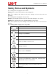
UTD2000 Series User Manual Safety Terms and Symbols The following terms may appear in this manual: Warning: The conditions and behaviors may endanger life. Note: The conditions and behaviors may cause damage to the product and other properties. The following terms may appear on the product: Danger: Performing this operation may cause immediate damage to the operator. Warning: This operation may cause potential damage to the operator.
UTD2000 Series User Manual Preface The Manual introduces information related to operation of digital storage oscilloscope of UTD2000 series user manual.
UTD2000 Series User Manual powerful functions required for faster completion of measurement tasks. User can observe faster signals on UTD200 series DSO by high-speed real time sampling and equivalent sampling. Clear LCD and mathematical operation functions make it easier for users to observe and analyze signal problems in a faster and clearer way. From the following parameter features, you can understand how this series of DSO can satisfy your measurement requirements. Two analog channels.
UTD2000 Series User Manual Contents Guaranty and Declaration .................................................................................................... 2 General Safety Overview ..................................................................................................... 4 Safety Terms and Symbols.................................................................................................. 6 Preface. .....................................................................................
UTD2000 Series User Manual 7.2 Voltage Parameter ................................................................................................ 38 7.3 Time parameter .................................................................................................... 39 Chapter VIII Cursor Measurement .................................................................................. 41 Chapter IX Storage and Load System ............................................................................ 41 9.
UTD2000 Series User Manual Chapter I Introduction This chapter introduces what users should pay attention to, front & rear panels, user interface and instruction of built-in system when using UTD 2000 series DSO first time. 1.1 General Inspection After purchasing a new UTD2000 DSO, we recommend you to inspect the instrument according to the following steps.
UTD2000 Series User Manual frequency defaults at 1kHz. Probe Compensation Siganl Tip Ground Terminal (4) Function Check Press AUTO (auto setting) button, square wave appears on the display screen, the wave range is about 3Vpp and the frequency is 1kHz. Go back to step 3 and check other channels in a same way. If the actual displayed waveform is different from above figure, please go to next step “Probe Compensation”.
UTD2000 Series User Manual Warning: In order to avoid electric shock when measuring high voltage with probe, please ensure that the insulation lead of the probe is in good condition and do not contact the metal part of the probe when connecting high pressure power supply. 1.
UTD2000 Series User Manual 1.4 Display (1) Display description Main time base setting Horizontal trigger area Time of center scale line Trigger state display Soft button menu corresponds to different buttons Channel 1 mark Waveform display window Channel 2 mark Vertical scale coefficient of channel (2) Soft button Press any soft button to activate corresponding menu. Symbols below may display on the menu: : There is next menu. : There is dropdown memu. : The menu has two options.
UTD2000 Series User Manual control area. Practices below will gradually guide you to get familiar with the controlling of the vertical system. Figure 1-6 Vertical Control Area on the Panel (1) Vertical POSITION: vertical position knob, user can change the current vertical position of channel waveform, the vertical position value will display on the baseline cursor area. Press this knob to get the dispayed channel position back to the vertical center.
UTD2000 Series User Manual 1. Use horizontal SCALE knob to change gear position settings of horizontal time base and observe the changes of state information. Turn horizontal SCALE knob to change “SEC/DIV” time base gear position, and you can find that corresponding changes have taken place in the time base gear position display of corresponding channel in the status bar. Horizontal scanning rate steps up in the multiple of 1, 2 and then 5 from 2ns to 50s. 2.
UTD2000 Series User Manual Chapter II Vertical System UTD2000 series DSO provides two analog input channels, each channel has an independent vertical menu. Each channel for UTD2000 series DSO can be set independently through the vertical system menu. After pressing CH1 or CH2 function key, the system shall display function menu of CH1 or CH2 channel. See Table 2-1 below for description.
UTD2000 Series User Manual Figure 2-1 Blocked DC Component of Signal Press F1 to select as DC coupling, you should be able to see both the DC and AC components of measured signals at CH1 channel as shown in figure below. Figure 2-2 Simultaneous Display of Signal DC and AC Components If you Press F1 to select as GND, to set CH1 to connect to the internal ground of the instrument, both DC and AC components of the input signal are blocked. And, waveform display is shown in figure below.
UTD2000 Series User Manual Figure 2-4 Waveform Display When Setting Bandwidth Limit as OFF Press F2 to set the BW Limit as 20MHz, the noises or high-frequency component over 20MHz in measured signal shall be attenuated, waveform display shown in figure below. BW Limit Mark Figure 2-5 Waveform Display When Setting Bandwidth throttling as ON 2.
UTD2000 Series User Manual Adjustments of vertical deflection factor V/div gear position can be set to coarse adjustment and fine adjustment. For coarse adjustment, V/div can be adjusted in step of multiple of 1, 2 and 5, the V/div range is 1mV/div~20V/div. Fine adjustments refer to changing deflection factor with smaller stepping within the current vertical gear position range. Vertical deflection factor can be consecutively adjusted within all vertical gears.
UTD2000 Series User Manual 2.6 Unit Press UNIT to set the unit as “V” or “A”, the default unit is V. After the unit is set, the unit on channel status tag will change accordingly. 2.7 Mathematical operation function Display results of CH1 & CH2 waveform mathematic operation (+、–、×、÷).
UTD2000 Series User Manual CH1 or CH2 CH2 Hanning Set to select Hanning, Hamming, Hamming Window Blackman, or Rectangle window Blackman function Rectangle Vrms Set vertical units as Vrms or dBVrms dBVrms Vertical unit Select FFT window Assuming that YT waveform is continuously repeated, DSO shall conduct FFT conversion for time record with finite length. In this case, when the cycle is an integer, YT waveforms are of the same amplitude at the starting and ending positions, without interrupting.
UTD2000 Series User Manual 2.9 Digital Filter Filter the frequency of specified waveband in signals by adjusting upper/lower frequency limit. Table 2-6 Digital Fiter Menu Function menu Setting Description Type Digital filter Digital filter CH1 Set CH1 as operation waveform CH2 Set CH2 as operation waveform Source Only when the signal frequency is Low pass lower than current upper frequency limit can the signal pass through.
UTD2000 Series User Manual Chapter III Horizontal System 3.1 Horizontal control (1) Horizontal control knob Change the horizontal time-base scale through SCALE knob, changing of horizontal scale can lead to expansion or shrink of waveforms relative to screen center. The horizontal system can be controlled by the following panel buttons/knobs.
UTD2000 Series User Manual 3.3 Window extension Extension window is used to enlarge the waveform so that users view the image details. The setting of window extension shall not be slower than that of main time base. Waveform horizontal extension part Extensive time base Main time base Waveform horizontal extension part Figure 3-2 Screen Display under Window Extension Under Window extension time base, there are two display areas, as shown in the figure above.
UTD2000 Series User Manual According to sin θ=A/B or C/D, θ is the angle difference of channels, the definition of A, B, C, D is shown in figure above, so the angle difference is: θ=±arcsin (A/B) or θ=±arcsin (C/D). If the elliptical axis lies on I, III quadrant, then the phase difference of angle should lie on I, IV quadrant, that is within (0~π/2) or (3π/2~2π). If the elliptical axis lies on II、IV quadrant, the phase difference of angle should be within (π/2~π) or (π~3π/2).
UTD2000 Series User Manual Chapter IV Trigger System When to collect data and display waveform depends on the trigger system. The DSO will convert the unstable displays into meaningful waveform after the trigger is set correctly. When the DSO start collecting data, it will firstly collect enough data to draw a waveform on the left of trigger. DSO will consecutively collect data while it waits the occurrence of trigger condition.
UTD2000 Series User Manual Set to automatic trigger. The DSO will continuously perform data acquisition AUTO without triggering signal. Mode Set to normal trigger. The DSO will only perform data acquisition when there is Normal triggering signal. Set to single trigger. The DSO will only perform 1 cycle of the data acquisition Single when there is triggering signal. AC Block the DC component of triggering signal.
UTD2000 Series User Manual Table 4-3 Pulse width setting menu Function Menu Setting Description Positive Set the positive pulse width as trigger signal Negative Set the negative pulse width as trigger signal Polarity > Trigger when pulse width is greater than the set value < Trigger when pulse width is less than the set value Pulse width condition <> Trigger when pulse width is in the range of set value.
UTD2000 Series User Manual The DSO generates a trigger when the slew rate of rising edge of signal is Rising < lower than the specified slew rate. The DSO generates a trigger when the slew rate of rising edge of signal is Rising <> higher than the specified lower-limit slew rate and lower than the specified upper-limit slew rate. The DSO generates a trigger when the slew rate of descending edge of signal Descending > is higher than the specified slew rate.
UTD2000 Series User Manual NTSC Applicable NTSC video signal. All line Set the video line to synchronous triggering. Set the video to sync and trigger on specific line, adjust through the Line multifunctional knob on front panel. Sync Odd field Set the video to sync and trigger on odd field. Even field Set the video to sync and trigger on even field. Line numbers Adjust through the multifunctional knob on front panel. Previous Go to previous page.
UTD2000 Series User Manual Figure 4-3 Observing Signals with Two Different Frequencies by Alternating Trigger Mode Table 4-7 Alternating Trigger Menu (Page 1) Function Setting Description Menu Type Alternating Channel CH1 Select CH1 as current channel selection CH2 Select CH2 as current channel Edge Set the edge as trigger mode Pulse width Set the pulse width as trigger mode Slope Set the slope as trigger mode DC Pass through DC and AC components of triggering signal.
UTD2000 Series User Manual 4.6 Trigger Holdoff Trigger holdoff time adjustment is used to observe complex waveform (pulse string series). Holdoff time refers to the waiting time for the DSO to restart trigger circuit. During holdoff time, the DSO will not trigger until the holdoff time is over. Table 4-9 Trigger Holdoff Menu Function Menu Setting Description Window extension On/off Press to turn on the main time base.
UTD2000 Series User Manual ■ External trigger: This type of trigger source can be used not only in collecting data in two channels but also in triggering the third channel at the same time. For example, the external clock or the signal from circuit to be measured can be served as trigger source. EXT trigger source use the external trigger signal connected to EXT TRIG junction. EXT can directly use the signal, the EXT can be used when the trigger level of signal ranges from -3V to +3V.
UTD2000 Series User Manual Chapter V Acquire System As shown in the figure below, the ACQUIRE on the control area is the function button of Acquire System. Figure 5-1 Function Key of Acquire System Press ACQUIRE button to enter data acquisition setting menu, set the data acquisition mode through menu control button. Table 5-1 Acquire Function Menu Function Menu Setting Description Sampling The DSO acquires data and reconstruct the waveform in the same time interval.
UTD2000 Series User Manual Figure 5-1 Non-average acquisition method Figure 5-2 Average acquisition of 8 numbers Notice: (1) Please select real-time sampling mode when observing single signal. (2) Please select equivalent sampling mode when observing high frequency periodic signal. (3) Please select peak detection mode when hoping to observe the signal envelope for any modulation signal.
UTD2000 Series User Manual Chapter VI Display System As shown in the figure below, the DISPLAY on the control area is the function button of Display System. Figure 6-1 Function Keys of Display System Press DISPLAY button to enter display setting menu as shown in the table below. Table 6-1 Display Menu (Page 1) Function Setting Description Vector Display sampled points in connection way. Dots Only display sampled data points.
UTD2000 Series User Manual Chapter VII Automatic Measurement UTD2000 series DSO support up to 34 types of waveform measurement parameters. Figure 7-1 Function Key of Auto Measurement 7.1 Measurement Menu Press MEASURE to enter Measurement menu. Table 7-1 Automatic measurement menu (Page 1) Function Menu Setting Description Main source CH1, CH2, MATH Select CH1 or CH2 as source. Slave source CH1, CH2, MATH Select CH1 or CH2 as source. OFF Close all display boxes of measurement parameters.
UTD2000 Series User Manual 7.2 Voltage Parameter Figure 7-2 Voltage Parameter Diagram Voltage parameters of UTD2000 series DSO include: Max value (Max): The voltage value from waveform highest level to GND. Min value (Min): The voltage value from waveform lowest level to GND. Top value (High): The voltage value from waveform flat top to GND. Bottom value (Low): The voltage value from waveform bottom to GND. Middle value (Middle): Half of the sum value of High and Low voltage value.
UTD2000 Series User Manual Frequency (Freq): The reciprocal of the period Rise time (Rise): The time for waveform amplitude to rise from 10% to 90%. Fall time (Fall): The time for waveform amplitude to fall from 90% to 10%. Rise delay: The time for main source and slave source to delay between two rising edges Fall delay: The time for main source and slave source to delay between two falling edges. Positive width (+Width): The positive pulse width at 50% amplitude.
UTD2000 Series User Manual Chapter VIII Cursor Measurement Use CURSOR to measure waveform X axis (time) and Y axis (voltage). Press CURSOR to enter cursor measurement menu. Figure 8-1 Function Key of CURSOR 8.1 Cursor measurement menu Press CURSOR to enter cursor measurement menu. Table 8-1 cursor measurement menu Function menu Setting Description Type OFF, time, voltage Set measurement type Mode Independent mode, tracking Select the moving mode of cursor.
UTD2000 Series User Manual Figure 8-2 Cursor measurement for time X time: Rotate Multipurpose knob to adjust the position of AX, press Multipurpose knob to adjust BX, shit between BX and AX with same way. A/B represents the time distance between zero point and the cursor A/B. B-A represents the difference beween cursor A and cursor B. 1/|B-A| represents the reciprocal of time difference. For same periodic signal, if AX and BX locate at adjacent rising edge, 1/|B-A| equal to frequency.
UTD2000 Series User Manual Chapter IX Storage The DSO setting, waveform and screen image can be store in DSO or USB, the stored setting or waveform can be recalled when needed. Press STORAGE to enter storage setting interface. Figure 9-1 Function Key of STORAGE 9.1 Set storage and load Press the Storage button, then Press F1 to choose storage type Setup, and you will see the following menu. Table 9-1 Storage setting menu Function Menu Setting Description Type Setup Select storage type as setup.
UTD2000 Series User Manual 9.2 Waveform storage and load Press the Storage button, then press F1 to choose storege type as Reference Waveform, and you will see the following menu. Table 9-2 Reference waveform menu (Page 1) Function Menu Setting Description Reference Type The selected storage type is reference waveform. waveform REF A Select load waveform to REF A. REF B Select load waveform to REF B. Source Close Close the loaded waveform. Storage Enter storage menu. Load Enter load menu.
UTD2000 Series User Manual Storage Press the button to store. 9.3 Bit map storage and load Press the Storage button, then press F1 to choose storege type Data File, and you will see the following menu. Table 9-6 Interface storage menu Function Menu Setting Description Type Data file The selected storage type is data file, stored in CSV format. Storage medium USB Only when the USB is plugged into DSO can the data file be stored. File name Customized Please refer section 9.1 “Edit file name”.
UTD2000 Series User Manual Chapter X Utility System Press UTILITY to enter utility menu. Figure 10-1 Function Key of UTILITY Table 10-1 Utility menu (Page 1) Function menu Setting Description System Config See chart 10-3 Enter system setup menu, the operation option include self-clibration, system information and clear information. Language Select interface language, different languages can be selected. Pass/Fail See chart 10-4 Recorder See chart 10-5 Enter pass/fail menu, please see “10.
UTD2000 Series User Manual 10.1 Pass/Fail Pass/Fail test: Detect whether or not the input signal is in the specified scope of template. If the input signal is within the scope, it is PASS, while if the input signal is out of the scope, it is FAIL. Pass/Fail interface on rear panel can output the Pass/Fail signal. Pass/FailOuput interface on rear panel. Press UTILITY button and then press F3 to enter Pass/Fail menu: (1) Turn on operation test, press F1 to set output condition.
UTD2000 Series User Manual tolerance. Load Load the reference waveform. Horizontal 1~255 Set horizontal tolerance of template through multifunctional knob. 1~255 Set vertical tolerance of template through multifunctional knob. tolerance Vertical tolerance Back Return to previous menu (Pass/Fail Test Menu). (8) Start the test, press F1 to conduct Pass/Fail test. 10.2 Recorder Record the current waveform frame by frame through waveform recording function.
UTD2000 Series User Manual 10.3 AUTO strategy As mentioned before, press AUTO button to activate the function of Waveform Auto Setting. To get a best diplay waveform, DSO automatically adjust vertical scale, horizontal time base and trigger mode based on input signals. This DSO allow users to set relevant parameters of auto setting function. Table 10-7 AUTO strategy menu Function Menu Setting Description Channel setup Release/Lock Release: The channel setting is set as default after AUTO operation.
UTD2000 Series User Manual Chapter XI Other function botton 11.1 AUTO Setting Based on input signals, Auto Setting selects appropriate time-based scale, Volt/Divs, trigger based to display waveform on the screen automatically. Press AUTO to enter automatic setting. AUTO Setting is only applicable to conditions below: 1) AUTO Setting is only applicable to signals with simple and single frequency. AUTO Setting is not effective for those complicated waveform.
UTD2000 Series User Manual 11.3 Help Menu Press the HELP key to go into help menu, then press any key will display the help information of this key. 11.4 Upgrade program The USB upgrade program makes upgrade easier and more flexible. To use this function, please follow the steps below: (1) Download a program file to be updated from internet and store the file in USB. (2) Turn off DSO and pulg USB into DSO, then turn on DSO.
UTD2000 Series User Manual Chapter XII Application example Example 1: Measuring simple signals To observe and measure an unknown circuit signal, and to quickly display and measure the signal's frequency and peak-to-peak value. (1) To quickly display this signal, follow the steps below: ① In the probe menu, set the attenuation factor to 10X and set the switch on the probe to 10X. ② Connect the CH1 probe to the circuitry point to be measured.
UTD2000 Series User Manual (1) To display CH1 and CH2 signals ① Press AUTO. ② Continue to adjust the horizontal and vertical range until you get the desired waveform display. ③ Press CH1 to select CH1. Adjust vertical position of the CH1 waveform by turning the vertical position control knob. ④ Press CH2 to select CH2. In the same way described above, adjust vertical position of the CH2 waveform so that the waveforms of CH1 and CH2 do not overlap, this will make observation easier. 2.
UTD2000 Series User Manual ① Press TRIG MENU in the trigger control zone to display the trigger setup menu. ② In this menu, use F1~F5 set the trigger type to EDGE, set trigger source to CH1, set inclination to Rising, set trigger type to Single and set trigger coupling to AC. ③ Adjust horizontal time base and vertical range to an appropriate range. ④ Turn the TRIGGER LEVEL control knob to get the desired level. ⑤ Press RUN/STOP and wait for a signal that meets the trigger condition.
UTD2000 Series User Manual (2) Connect the signal to ensure stable display of waveform. (3) Improving trigger by setting trigger coupling. ① Press TRIG MENU in the trigger zone to display the trigger setup menu. ② Set trigger coupling to Low Frequency Holdoff or High Frequency Holdoff. Low frequency holdoff is seting up a high-pass filter. It filters low frequency signal component under 80kHz and allows high frequency signal component to pass through. High frequency holdoff is setting up a low-pass filter.
UTD2000 Series User Manual Measuring one step voltage of the step signal To measure one step voltage of the step signal, follow the steps below: 1. Press CURSOR to display the cursor measurement menu. 2. Press menu operation key F1 to set cursor type to VOLTAGE. 3. Turn the multifunction control knob to set cursor 1 at one step voltage of the step signal. 4. Press SELECT to select the cursor, then turn the multifunction control knob again to set cursor 2 at another step voltage of the step signal.
UTD2000 Series User Manual Chapter XIII System Prompts and Troubleshooting 13.1 Definitions of System Prompts Adjustment at Ultimate Limit: This informs you that the multifunction control knob has reached its adjustment limit in the current status. No further adjustment is possible. When the vertical deflection factor switch, time base switch, X shift, vertical shift and trigger level adjustments have reached their ultimate limits, this prompt will appear.
UTD2000 Series User Manual or to filter any high or low frequency noise that is interfering with triggering. (4) Slow refresh ①. Check if the acquiring mode in ACQUIRE button menu is average, and the average times are large. ②. If increasing the refresh speed is needed, please decrease the average times appropriately or select other acquiring modes, i.e. normal sampling. ③. Check if the persistence in DISPLAY button menu is set relatively long or infinite. (5) The waveform is like stair-step shape. ①.
UTD2000 Series User Manual Chapter XIV Technical Information Except for those specifications marked with “Typical”, all specifications have warranties. Unless otherwise specified, all technical specifications are applicable to the probes with attenuation switch set as 10× as well as UTD2000 series DSO. DSO must first meet the following two conditions to meet those specification standards: The instrument must continuously operate for over half an hour within the operating temperature.
UTD2000 Series User Manual Measurement Single time: ± (1 sampling time interval+50ppm×reading+0.6ns) accuracy of time >16 average values: ± (sampling time interval+50ppm×reading+0.4ns) interval (△T) (full bandwidth) Vertical UTD2202 UTD2052 UTD2072 UTD2102PRO Model UTD2102 UTD2152 CEX+ CEX+ CEX UTD2202 UTD2152CL CL+ CL UTD2102CL+ PRO Analog Bandwidth Rise Time(Typical) Channels 50MHz 70MHz 100MHz 150MHz 100MHz 150MHz 200MHz ≤7ns ≤7ns ≤3.5ns ≤2.4ns ≤3.5ns ≤2.4ns ≤1.
UTD2000 Series User Manual accuracy of quantity of ≥16, the voltage difference (ΔV) between any two points on the waveform: ± voltage difference (3%×reading+0.05div) (△V) (average sampling mode) Trigger System Specifications Trigger sensitivity ≤1div Interior:From the screen center ±10div Range of trigger level EXT: ± 3V Trigger level accuracy Interior:±(0.
UTD2000 Series User Manual Measurements Manual mode Voltage difference between cursors (△V), Time difference between cursors (△T), Cursor Reciprocal of △T (Hz) (1/△T)) Track mode Voltage value and time value of point of waveform. Auto measurement Cursor display is allowed on auto measurement mode.
UTD2000 Series User Manual Display Displays types LCD with Diagonal of 178mm (7-inch) Display resolution 800 horizontal×RGB× 480 vertical pixels Display color Color Waveform luminance Adjustable Backlight intensity (Typical) 300nit Language Chinese and English Interface function: Standard configuration Standard:USB-Host, USB-Device, EXT Trig, Pass/Failt. Option:Multimeter module (UT-M12), LAN.
UTD2000 Series User Manual Chapter XV Appendix Appendix A Accessories UTD2052CL+ (50 MHz) UTD2072CL (70 MHz) Model UTD2102CL+ (100 MHz) UTD2102CL PRO (100 MHz) UTD2152CL (150 MHz) UTD2102CEX+ (100 MHz) UTD2152CEX (150 MHz) UTD2202 PRO(200 MHz) UTD2202CEX+ (200 MHz) A string of power cord complying with country standard.
UTD2000 Series User Manual years from the date of shipment by the authorized dealer. If any such product proves defective during this warranty period, UNI-T will repair the defective product or provide a replacement according to specific terms and conditions of the warranty. To request maintenance and repair service or a full copy of the warranty, please contact your nearest UNI-T sales and maintenance office.