
User Guide


17
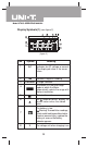
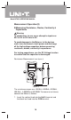
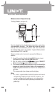
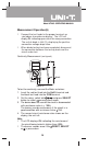
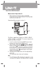
Measurement Operation(4)
2. Set the rotary switch toΩ , resistance
measurement (Ω) is defaults or press SELECT button
to select Ω measurement mode.
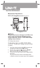
3. Connect the test leads across with the object being
measured.
The measured value shows on the display.
Note
l The test leads can add 0.1Ωto 0.2Ωof error to
resistance measurement. To obtain precision readings
in low-resistance measurement, that is the range of
400.0Ω, short-circuit the input terminals beforehand,
using the relative value function button RESET to
automatically subtract the value measured when the
testing leads are short-circuited from the reading.
l For high-resistance measurement (>1MΩ), it is normal
taking several seconds to obtain a stable reading.
l IfΩ reading with shorted test leads is not 0.5Ω,
check for loose test leads, incorrect function selection,
or enabled Data Hold function.
l The LCD displays OL indicating open-circuit for the
tested resistor or the resistor value is higher than the
maximum range of the Meter.
l When resistance measurement has been completed,
disconnect the connection between the testing leads
and the circuit under test.
Model UT90C: OPERATING MANUAL